Vibration-damping control device for vehicle

A technology for a control device and a vehicle, which is applied in the direction of the control device, vehicle components, engine control, etc., can solve problems such as fluctuation, reduction of the frequency of vibration reduction control execution, and undocumented recovery methods.

Active Publication Date: 2013-01-16
NISSAN MOTOR CO LTD
View PDF6 Cites 7 Cited by
  • Summary
  • Abstract
  • Description
  • Claims
  • Application Information

AI Technical Summary

Problems solved by technology

[0003] However, in the technology described in the above-mentioned Patent Document 1, there is no description of a specific recovery method after reducing the control gain.
Therefore, there is a possibility that fluctuations after control restoration may recur, and there is a problem that the execution frequency of vibration reduction control may decrease when the operation of vibration reduction control is stopped for a long period of time to prevent recurrence.

Method used


Image

  • Vibration-damping control device for vehicle
  • Vibration-damping control device for vehicle
  • Vibration-damping control device for vehicle

Examples


Embodiment 1

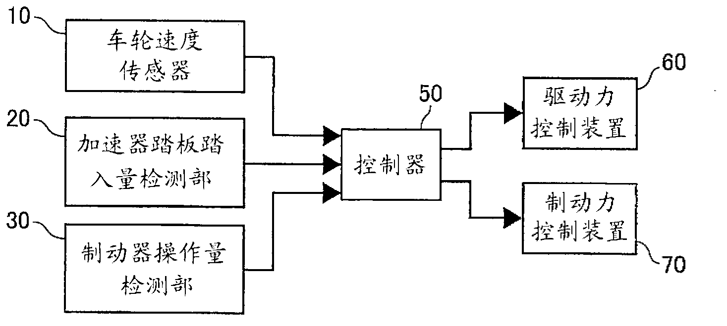
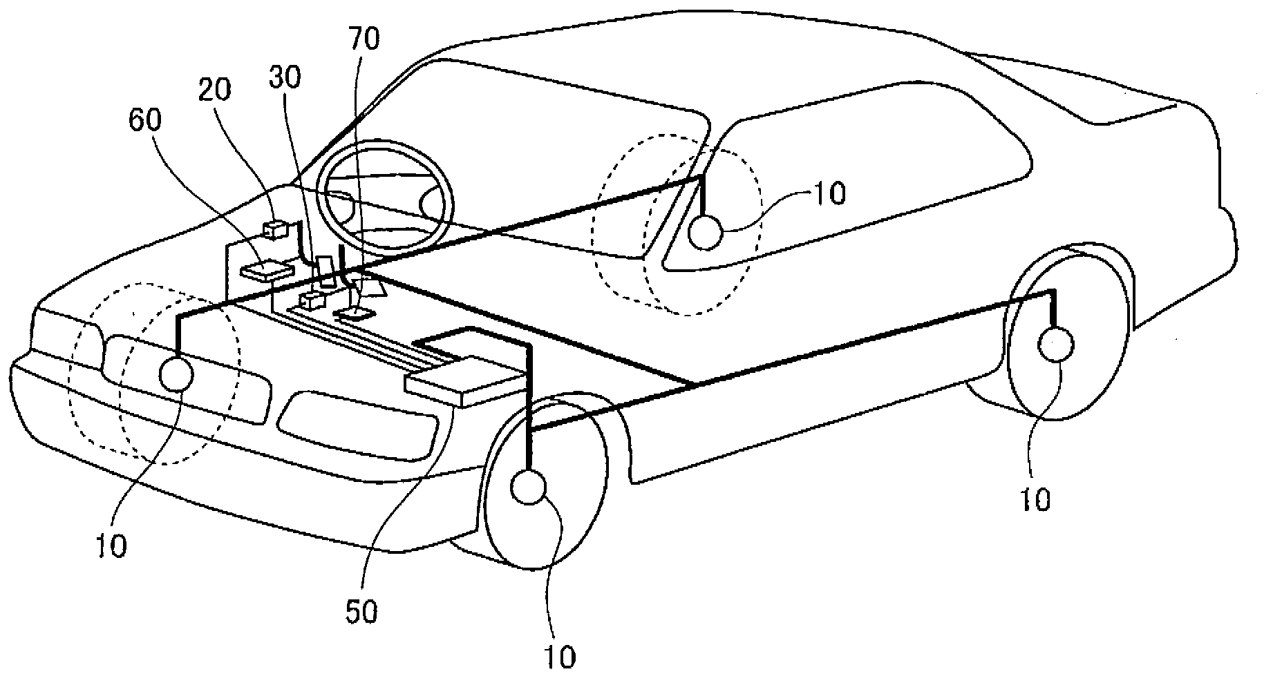
[0035] figure 1 is a system diagram showing the configuration of the vibration damping control device of Embodiment 1, figure 2 It is a configuration diagram of a vehicle equipped with a vibration damping control device. First, the configuration of the vibration damping control device will be described. The wheel speed sensor 10 detects the speed of each wheel from the number of rotations of each wheel. The accelerator pedal depression amount detection unit 20 detects an accelerator opening APO indicating the depression amount of the accelerator pedal depressed by the driver. The brake operation amount detection unit 30 detects the brake operation amount S_b (brake pedal stroke amount, pedaling force, etc.) by the driver.

[0036] The controller 50 outputs control signals to the driving force control device 60 and the braking force control device 70 which are actuators of the vibration damping control device based on the state quantities detected by the sensors. The contr...

Embodiment 2

[0182] Next, Example 2 will be described. The basic configuration is the same as that of Embodiment 1, so only the different points will be described. Figure 19 It is a flowchart showing output adjustment gain and output mode setting processing in the second embodiment. The fluctuation detection processing in step 720 is the same as that in the first embodiment, and therefore description thereof will be omitted.

[0183] In step S730, based on the result of the fluctuation detected in step S720, the output-adjusted correction torque dTw in the fluctuation judgment is calculated 1 * The maximum amplitude and duration of fluctuations. Figure 20 It is a flowchart showing the processing procedure of the vibration damping control processing of the controller of the second embodiment.

[0184] In step S730 - 1 , it is determined whether any one of the upper limit threshold reached flag fHunt_U, the lower limit threshold reached flag fHunt_L, and the fluctuation flag fHunt is 1....


PUM


Abstract

A vibration-damping control device for a vehicle calculates the correction torque which could suppress the vibration on the spring of a vehicle body. Upon outputting a correction torque command value to a braking / driving torque generating means, the vibration-damping control device outputs a hunting-period correction torque command value, which is smaller than the normal-period correction torque command value, if the vibration of the correction torque is at a predetermined vibration or more and continues for a predetermined time period. Subsequently, if the vibration of the correction torque is at a predetermined vibration or less and continues for a first predetermined time period, the output of the correction torque command value is reverted to the normal-period correction torque command value from the hunting-period correction torque command value. The frequency of executing vibration-damping control is increased by preventing the occurrence of hunting when the vibration-damping control is reverted to a normal control.

Description

technical field [0001] The present invention relates to a vibration damping control device for suppressing vibration generated in a vehicle. Background technique [0002] Currently, there is a technique to reduce the control gain when the vibration amplitude of the vibration damping torque is greater than or equal to a predetermined amplitude and continues for a predetermined time as the input value of the driving torque and the wheel rotation speed to calculate the damping torque for suppressing the sprung vibration. , the technique described in Patent Document 1 is known. [0003] However, in the technology described in the above-mentioned Patent Document 1, there is no description of a specific recovery method after reducing the control gain. Therefore, there is a possibility that fluctuations after control restoration may recur, and there is a problem that the execution frequency of vibration reduction control decreases when the operation of vibration reduction control ...

Claims


Application Information

Patent Timeline
Patent Type & Authority Applications(China)
IPC IPC(8): F02D29/02B60W30/20B60W50/06
CPCB60L2240/423B60W2050/0024B60W2050/0033B60W10/04B60W30/02B60W30/20B60W2030/041B60W10/18Y02T10/642B60W10/08B60W2710/083B60W20/00B60W50/06B60W2050/0083B60L2270/147Y02T10/64B60W2520/30B60W20/15B60W20/11
Inventor 小林洋介木村健盐泽裕树太田光纪佐佐木博树伊藤明弘吉泽正彦
Owner NISSAN MOTOR CO LTD
Why Eureka
Try Eureka