Eureka AIR delivers breakthrough ideas for toughest innovation challenges, trusted by R&D personnel around the world.

Electric excavator weighing method

An electric excavator and weighing technology, applied in the direction of weighing, instruments, etc., can solve the problems of not being suitable for wire ropes, large thrust errors, and material weight errors

Active Publication Date: 2013-01-23
中钢集团衡阳机械有限公司
View PDF4 Cites 10 Cited by
  • Summary
  • Abstract
  • Description
  • Claims
  • Application Information

AI Technical Summary

Problems solved by technology

[0004] Although the technical solution of this patent saves manpower, the calculation method ignores the influence of the gravity of the shovel rod and other parts attached to the shovel rod, so the material weight calculated according to this technical solution will have a relatively large error, and the patent The technical solution is not suitable for the electric shovel pushed by the wire rope
[0005] In addition, in this technical solution, the lifting force of the wire rope on the bucket and the thrust of the pushing arm on the bucket are respectively calculated through the relationship between these two forces and the lifting torque and pushing torque. The transmission efficiency between the motor and the output of the working mechanism is often changed, but they all take a fixed value in the calculation, so the lifting force of the steel wire rope on the bucket and the force of the pushing arm on the bucket are calculated in this way. Thrust error is relatively large

Method used


Image

  • Electric excavator weighing method
  • Electric excavator weighing method
  • Electric excavator weighing method

Examples


Embodiment Construction

[0059] Below in conjunction with embodiment the scheme of the present invention is described further

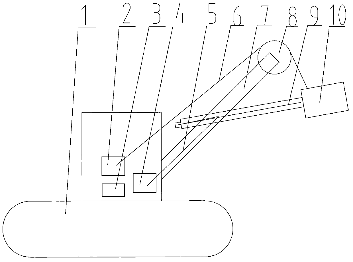
[0060] Such as figure 1 As shown, an electric excavator generally consists of a traveling mechanism 1, a lifting mechanism 2, a slewing mechanism 3, a pushing mechanism 4 and electrical parts. The walking mechanism 1 brings the electric excavator to the excavation destination; the pushing mechanism 4 pulls the pushing wire rope 5 to push the bucket 10 fixedly installed on the shovel rod 9 to shovel into the ore body; the lifting mechanism 2 pulls the lifting wire rope 6 and lifts it up for fixed installation The bucket 10 on the shovel bar 9 makes the ore fill the bucket 10 and stay at a height higher than the body of the electric wheel dump truck; the slewing mechanism 3 rotates the bucket 10 filled with ore from the side of the ore body to the electric wheel On the side of the dump truck, then the bucket 10 is opened, and the ore is poured into the dump truck, then the ele...


PUM


Abstract

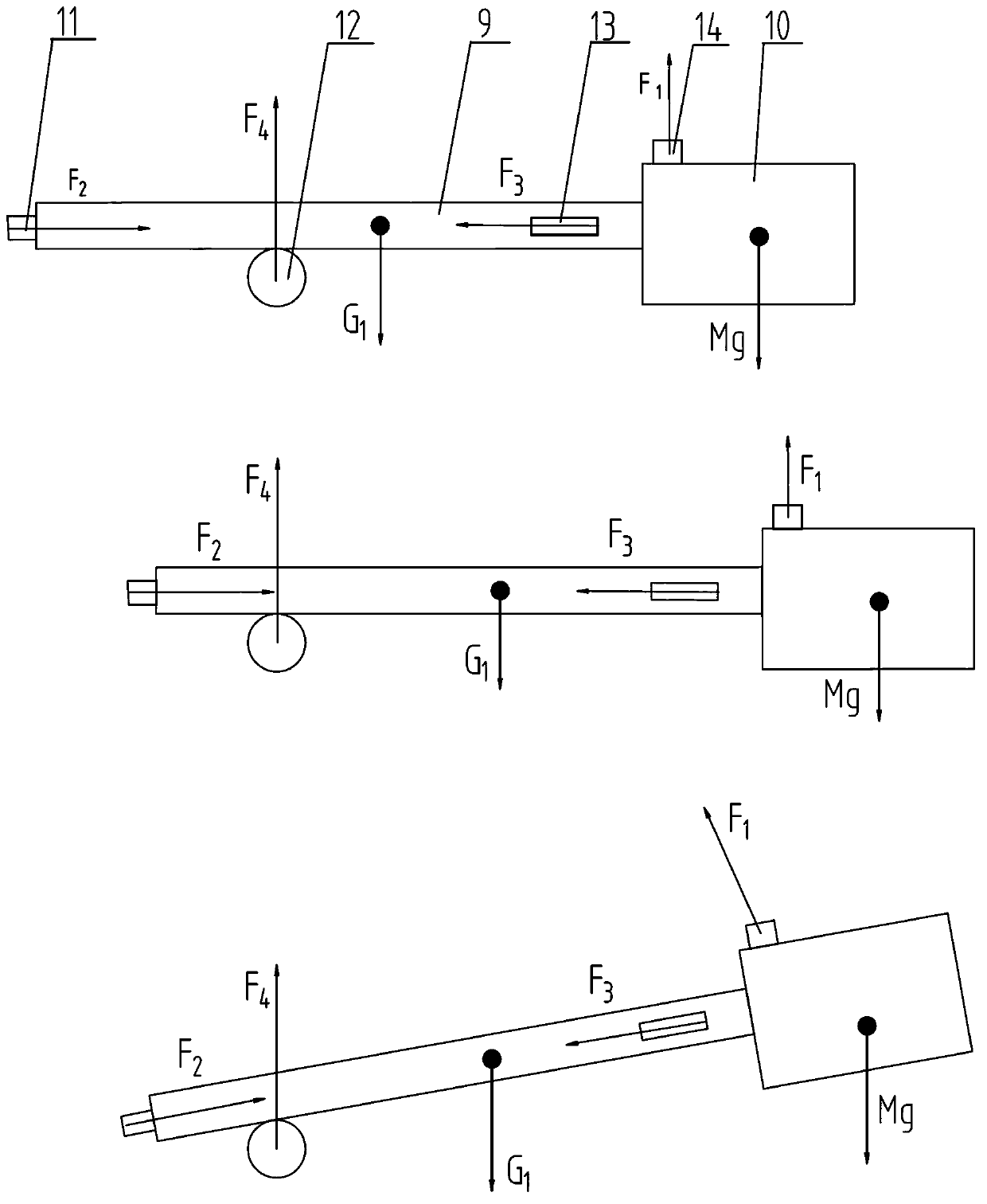
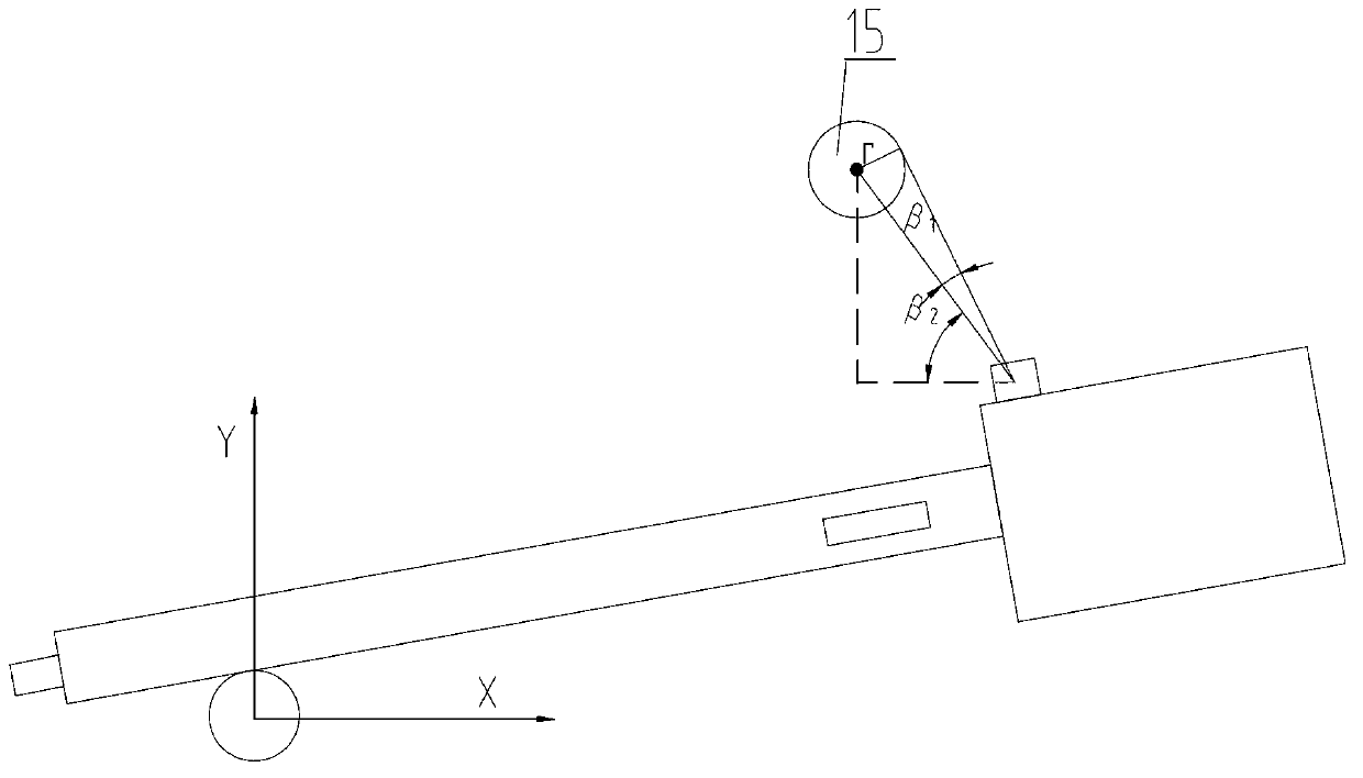
The invention discloses an electric excavator weighing method for solving the technical problem of overlarge weighing error of the existing method. According to the technical scheme of the invention, the electric excavator weighing method comprises the following steps of: establishing a rectangular coordinate system by taking the center of a saddle as a moment balance point and taking the moment balance point as an original point; determining coordinates of the centers of gravities of a shovel lever, a part attached to the shovel lever and a bucket full of materials as well as action points of a lifting force and a pushing force in the coordinate system when the shovel lever is in a horizontal position, and then, solving the coordinates of the points during weighing according to a shovel lever movement locus equation, wherein the moment arm of the pushing force is equal to the vertical coordinate of the action point of the pushing force, and the moment arm of the gravity is equal to the horizontal coordinate of the center of gravity in weighing; solving the coordinate of a tangency point according to the position relationship between the action point of the lifting force as well as a hoisting rope at the right of the head sheave and the tangency point of the head sheave during weighing, listing an equation of a straight line where the hoisting rope is, and solving the moment arm of the lifting force by utilizing the distance from the center of the saddle to the straight line; measuring the pushing force and the lifting force by using a sensor; and finally, listing a torque equilibrium equation and solving the weight of the materials.

Description

technical field [0001] The invention relates to a weighing method of an electric excavator, which is especially suitable for weighing the twist-free round shovel type electric excavator. Background technique [0002] Electric excavators are mainly used for excavating soil, rock, ore and coal in large-scale open-pit mines. According to different pushing methods, they are divided into rack and pinion push electric excavators and twist-free round shovel-bar electric excavators. In the past, in order to count the output of a single excavator, it could only be estimated by special personnel to record the number of loaded vehicles. This not only has many errors in the statistics, but also increases the investment of personnel. [0003] The Chinese patent with the application number 200710185462.5 announced a weighing method for a rack and pinion push type electric excavator. This method calculates the weight of the wire rope against the shovel through the relationship between the ...

Claims


Application Information

Patent Timeline
IPC IPC(8): G01G9/00
Inventor 崔崴宋春根
Owner 中钢集团衡阳机械有限公司
Why Eureka
Eureka Blog
Learn More