Flexible thermoelectric conversion system and manufacturing method thereof

A technology of thermoelectric conversion and manufacturing method, which is applied in the direction of thermoelectric device parts, electrical components, generators/motors, etc., can solve the problems of inability to use pipelines, etc., and achieve the effects of increasing application range, simple process steps, and reducing manufacturing costs

Active Publication Date: 2013-01-23
中科芯未来微电子科技成都有限公司
View PDF5 Cites 6 Cited by
  • Summary
  • Abstract
  • Description
  • Claims
  • Application Information

AI Technical Summary

Problems solved by technology

However, its application range is limited by the characteristics of materials such as ceramics and the supporting boost circuit PCB board, so it cannot be applied to places that require certain bending, such as pipelines.

Method used


Image

  • Flexible thermoelectric conversion system and manufacturing method thereof
  • Flexible thermoelectric conversion system and manufacturing method thereof
  • Flexible thermoelectric conversion system and manufacturing method thereof

Examples


Embodiment 1

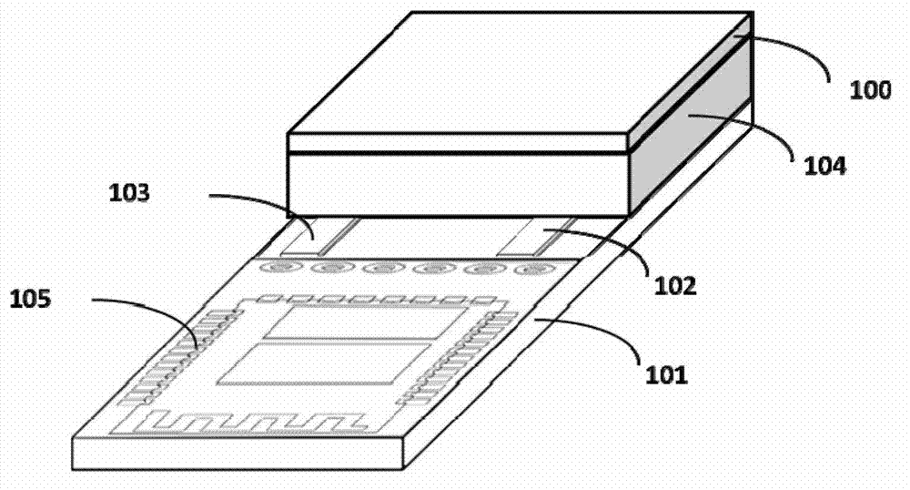
[0046] Such as image 3 with Figure 7 Shown: is a schematic structural diagram of a flexible thermoelectric conversion system. In this embodiment, the flexible thermoelectric conversion system includes a first flexible power generation generator 10 and a flexible conversion circuit for converting and outputting electrical energy from the first flexible thermoelectric generator 10, where The first flexible thermoelectric generator 10 includes a first flexible substrate 100 and a second flexible substrate 101 located under the first flexible substrate 100, and the first flexible substrate 100 and the second flexible substrate 101 are arranged between A number of alternately distributed N-type thermoelectric material particles 301 and P-type thermoelectric material particles 302, the N-type thermoelectric material particles 301 passing through the first conductive connection layer 201 and the second flexible substrate on the first flexible substrate 100 The second conductive conne...

Embodiment 2

[0064] Such as Figure 8 Shown: the schematic diagram of the structure of the flexible thermoelectric conversion system of this embodiment, Picture 9 This embodiment is a schematic structural diagram of the second flexible thermoelectric generator 20 included in the flexible thermoelectric conversion system. In this embodiment, in order to achieve good heat conduction with the outside, the first flexible substrate 100 of the second flexible thermoelectric generator 20 A through hole 401 penetrating through the first flexible substrate 100 is provided, and the through hole 401 is located directly above the N-type thermoelectric material particle 301 or the P-type thermoelectric material particle 302. At the same time, the through hole 401 can also be At the same time, it is located directly above the N-type thermoelectric material particles 301 and the P-type thermoelectric material particles 302.

[0065] Further, the second flexible substrate 101 may also be provided with a thro...

Embodiment 3

[0068] Such as Picture 10 Shown: the schematic diagram of the structure of the flexible thermoelectric conversion system of this embodiment, Picture 11 It is a schematic diagram of the structure of the third flexible thermoelectric generator 30 included in the flexible thermoelectric conversion system in the embodiment of the present invention. In this embodiment, the third flexible thermoelectric generator 30 is in the first flexible substrate 100 and the second flexible substrate. A through hole 401 is provided on the first flexible substrate 100 at the same time. The through hole 401 on the first flexible substrate 100 is located directly above the N-type thermoelectric material particles 301 and / or the P-type thermoelectric material particles 302; on the second flexible substrate 101 The through holes 401 are located directly below the N-type thermoelectric material particles 301 and / or the P-type thermoelectric material particles 302. Then, the through hole 401 is filled ...


PUM


Abstract

The invention relates to a flexible thermoelectric conversion system and a manufacturing method of the flexible thermoelectric conversion system. The flexible thermoelectric conversion system comprises a flexible thermoelectric generator and a flexible conversion circuit. The flexible thermoelectric generator comprises a first flexible substrate and a second flexible substrate. A plurality of alternately distributed N-type thermoelectric material particle bodies and P-type thermoelectric material particle bodies are arranged between the first flexible substrate and the second flexible substrate. After being connected with the P-type thermoelectric material particle bodies in series, the N-type thermoelectric material particle bodies are electrically connected with the P-type thermoelectric material particle bodies through a first conductive connecting layer on the first flexible substrate and a second conductive connecting layer on the second flexible substrate so as to form thermoelectric material bodies between the first flexible substrate and the second flexible substrate. The thermoelectric material bodies are packaged between the first flexible substrate and the second flexible substrate through flexible insulation heat-insulation potting material bodies. The flexible conversion circuit is electrically connected with the thermoelectric material bodies. The flexible thermoelectric conversion system has the advantages of simple and convenient process, low manufacturing cost, high generating efficiency, and safety and reliability, and the application range of thermoelectric generators is expanded.

Description

Technical field [0001] The invention relates to a thermoelectric conversion system, in particular to a flexible thermoelectric conversion system and a manufacturing method thereof, and belongs to the technical field of thermoelectric conversion. Background technique [0002] Due to the increasing miniaturization trend of portable electronic products, the research and development of miniaturized power supplies have been promoted. As a self-sufficient energy source, thermoelectric generators can directly convert thermal energy into electrical energy according to the Seebeck effect, and can maintain a practically unlimited useful life at a suitable temperature. This makes it a high-tech in the energy field. One of the hot spots of international research. [0003] The thermoelectric generator is generally composed of three parts: heat source, heat sink and thermopile. A thermopile is composed of a series of thermoelectric pairs that can convert thermal energy into electrical energy (...

Claims


Application Information

Patent Timeline
Patent Type & Authority Applications(China)
IPC IPC(8): H01L35/02H02N11/00
Inventor 吴庆曹二林王润兰陈岚
Owner 中科芯未来微电子科技成都有限公司
Why Eureka
Try Eureka