
Retainer for adjustment device of friction clutch, and friction clutch

A friction clutch, compensation adjustment technology, applied in the direction of friction clutch, clutch, mechanical drive clutch, etc., can solve the problem of reduced friction torque, no longer able to transmit, etc.

Active Publication Date: 2013-01-23
SCHAEFFLER TECH AG & CO KG
View PDF6 Cites 1 Cited by
  • Summary
  • Abstract
  • Description
  • Claims
  • Application Information

AI Technical Summary

Problems solved by technology

It is also possible that due to a fault the friction disk is oiled and can no longer transmit the desired torque because the transmittable friction torque is reduced

Method used


Image

  • Retainer for adjustment device of friction clutch, and friction clutch
  • Retainer for adjustment device of friction clutch, and friction clutch
  • Retainer for adjustment device of friction clutch, and friction clutch

Examples


Embodiment Construction

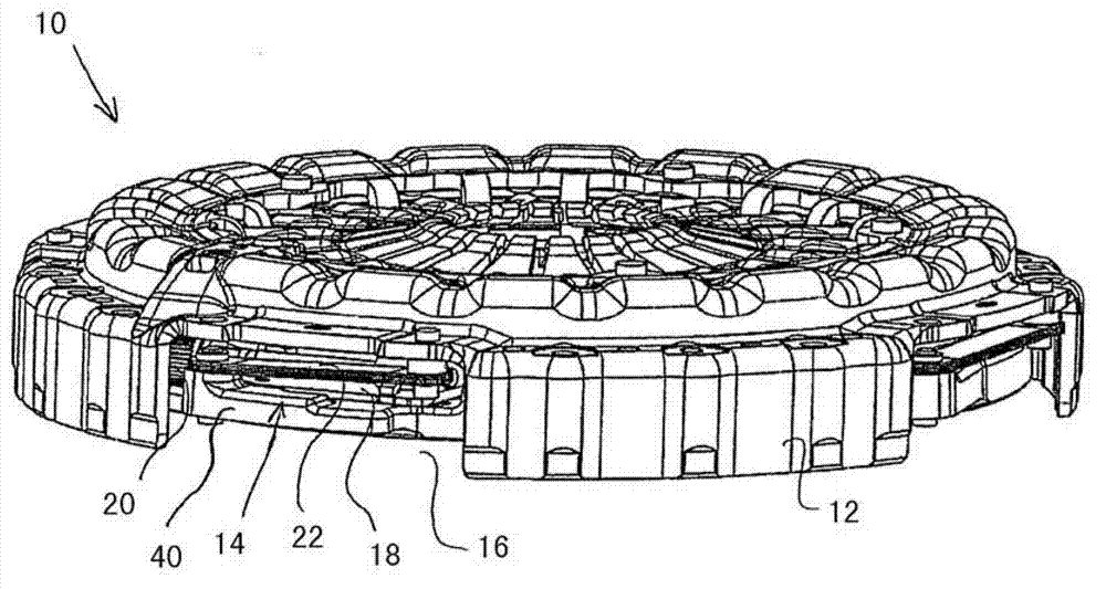
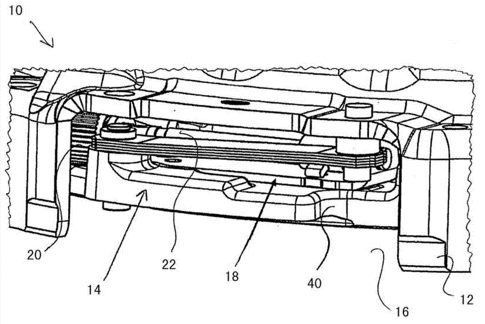
[0029] figure 1 and figure 2 The friction clutch 10 shown in has a clutch housing 12 which has a service opening 16 in the region of an adjusting unit 14 for wear-induced maintenance of a pressure plate 40 movable relative to a counter pressure plate. The mis-spacing is compensated to squeeze the clutch plate between the counter plate and the pressure plate 40 . Visible through the service opening 16 is a cage 18 which carries a threaded spindle 22 connected to a pinion 20 .

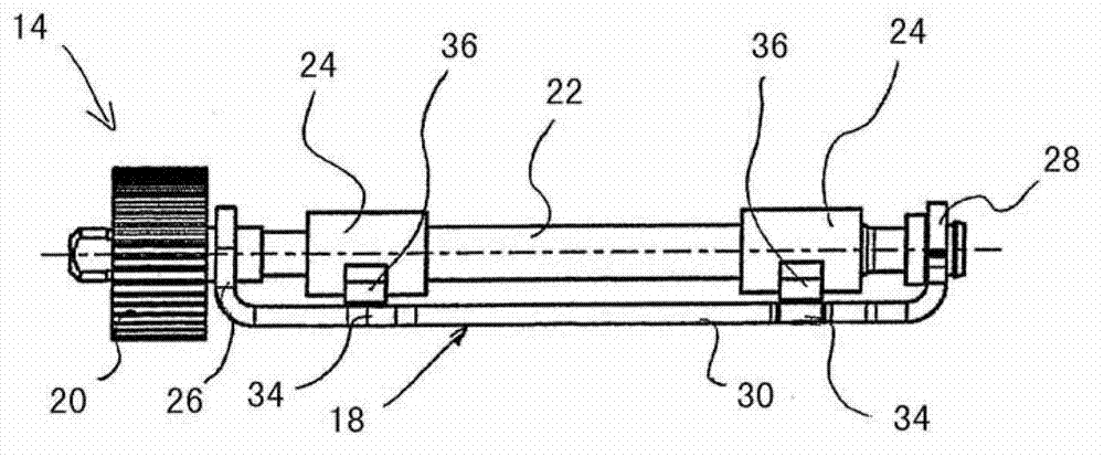
[0030] Such as image 3 and 4 As shown, a screw nut 24 is screwed on the lead screw 22, and the lead screw nut 24 can move from the original position (left position) without friction lining wear in the axial direction along the lead screw 22 to the friction End position with fully worn lining (right position). The cage 18 has a first retaining arm 26 and a second retaining arm 28 to support the lead screw 22 . The first retaining arm 26 and the second retaining arm 28 are connected to each other i...


PUM


Abstract

The invention relates to a retainer for an adjustment device of a friction clutch, comprising a first retaining arm for supporting a spindle, which is connected to a pinion and which axially moves a spindle nut screwed onto the spindle, and a second retaining arm for supporting the spindle, the second retaining arm being arranged at a distance from the first retaining arm. Furthermore, a fastening piece is provided, which extends between the first retaining arm and the second retaining arm and fastens the retainer to a part of the ramp system. According to the invention, the fastening piece has at least one marking for associating the position of the spindle nut with a wear state of the friction clutch. Thus, the wear state of the friction clutch can be indicated, so that the fault analysis of the friction clutch is simplified and the maintenance friendliness of the friction clutch is increased.

Description

technical field [0001] The invention relates to a cage for a friction clutch compensation adjustment device and a friction clutch, wherein a threaded screw can be held by means of the cage, by means of which the wear of the friction lining of the friction clutch can be prevented. Compensate for the stroke increase of the pressure plate relative to the counter pressure plate. Background technique [0002] In order to compensate for the wear that occurs on the friction linings, the friction clutch can be effectively controlled by a compensating adjustment device. Here, an unfavorable increase in the pressing force of an operating system (for example a disc spring) that acts on the counterplate of the friction clutch to move the pressure plate due to wear is sensed, and a compensating adjustment is brought about as a function of the pressing force. Alternatively, a misalignment distance between the clutch housing and the operating system that occurs due to wear of the friction...

Claims


Application Information

Patent Timeline
IPC IPC(8): F16D13/75
CPCF16D13/757
Inventor M·施奈德G·阿纳特
Owner SCHAEFFLER TECH AG & CO KG
Learn More