
Method and tool for mounting brake system pipeline of aluminum alloy vehicle

A vehicle braking and braking system technology, which is applied in the field of rail vehicles, can solve problems affecting the air tightness of pipelines, waste of human resources, pipeline deformation, etc., and achieve the goal of improving installation efficiency, simplifying installation steps, and improving installation conditions Effect

Inactive Publication Date: 2013-01-30
CRRC DALIAN CO LTD
View PDF6 Cites 8 Cited by
  • Summary
  • Abstract
  • Description
  • Claims
  • Application Information

AI Technical Summary

Problems solved by technology

[0004] Due to the existence of the vehicle underframe beam, the pipeline can be temporarily erected in the oval hole of the underframe beam, which is convenient for assembly. The disadvantage of this assembly scheme is that it is difficult to determine the location of the pipeline, which can only be measured on site, and the error is relatively large , after all the pipelines are adjusted and connected, the pipe clips can be fastened, which is difficult to operate and wastes man-hours. For stainless steel vehicles, this assembly method can only be used; for aluminum alloy vehicles, this assembly scheme is more difficult. Operation, due to the existence of the elliptical hole in the crossbeam without the bottom frame, and the size of the large row of pipelines is long, when assembling, it needs many people to lift, lift and other human-assisted forms to assemble the pipelines, resulting in a waste of human resources, and because the pipe wall Thinner and lower strength, it is easy to deform the pipeline, pipeline positioning and installation of pipe joints, which directly affects the airtightness of the pipeline

Method used


Image

  • Method and tool for mounting brake system pipeline of aluminum alloy vehicle
  • Method and tool for mounting brake system pipeline of aluminum alloy vehicle
  • Method and tool for mounting brake system pipeline of aluminum alloy vehicle

Examples


Embodiment Construction

[0026] like Figure 8 As shown, the embodiment of the present invention provides an aluminum alloy vehicle brake system pipeline installation method, including the following steps:

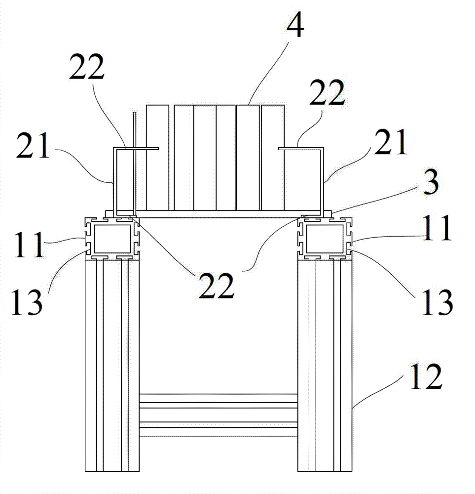
[0027] S1: Make the tooling, the structure of the tooling is as follows Figure 1-3 As shown, the tooling is composed of a base frame 1, a plurality of pipe holder brackets 2 installed on the base frame along the length direction of the base frame 1, and a plurality of positioning baffles 4 for positioning one end of the brake system pipeline. The baffles 4 are all vertically placed on the end plate 3 at one end of the chassis 1, wherein the position of the tube holder bracket 2 is adapted to the hoisting position on the bottom of the aluminum alloy vehicle;

[0028] S2: install the tube holders 20 on the brackets 2 of the tube holders respectively and fasten them;

[0029] S3: arranging the tube clips 10 on each tube clip holder 20 as required;

[0030] S4: Connect the brake system pipeline 40...


PUM


Abstract

The invention provides a method and tool for mounting a brake system pipeline of an aluminum alloy vehicle. The method comprises the following steps of: manufacturing the tool; arranging pipe clamp anchors on pipe clamp anchor brackets respectively and fastening; arranging pipe clamps on the pipe clamp anchors according to a requirement; connecting the brake system pipeline and contacting end parts of the brake system pipeline with positioning baffle plates; fixing the brake system pipeline on the pipe clamp anchors by using the pipe clamps; performing wind pressure test on the brake system pipeline to check the airtightness of the pipeline; disassembling a whole body which consists of the pipe clamp anchors, the pipe clamps and the brake system pipeline from the pipe clamp anchor brackets; and hoisting the whole body to the bottom of the aluminum alloy vehicle. By the technical scheme, the brake system pipeline can be preassembled on the ground, the overall pipeline can be assembled into a module which is completely matched with a chassis of a vehicle by using the pipe clamps and the pipe clamp anchors, and the module is hoisted to a hoisting position of a frame. The method is easy to operate and high in mounting efficiency.

Description

technical field [0001] The invention relates to rail vehicle technology, in particular to a pipeline installation method and tooling for an aluminum alloy vehicle braking system. Background technique [0002] The pipeline of the rail vehicle braking system is used as a tool for the pneumatic device to transmit air. Its airtightness directly affects the performance of the braking system. It runs through the whole section of the vehicle. If the traditional pipeline assembly method is used, the pipelines are assembled one by one on the vehicle. After all the pipelines are connected, the pipe clamps are tightened again. This requires the cooperation of multiple people to complete, which is not only difficult to operate, but also wastes A large number of working hours will conflict with other processes, which is more likely to cause pipeline leakage, make it difficult to find, and affect the production schedule. [0003] The existing technical solution is to put all the pipes in...

Claims


Application Information

Patent Timeline
Patent Type & Authority Applications(China)
IPC IPC(8): B25B11/00
Inventor 张天朋盛朝霞付建鹏项宇航
Owner CRRC DALIAN CO LTD
Learn More