Scara robot
A robot and joint-type technology, applied in the direction of manipulators, program-controlled manipulators, manufacturing tools, etc., can solve problems such as labor and time
- Summary
- Abstract
- Description
- Claims
- Application Information
AI Technical Summary
Problems solved by technology
Method used
Image
Examples
no. 1 approach )
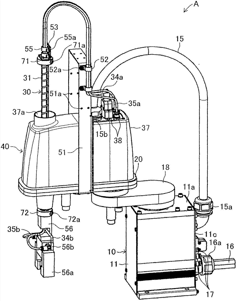
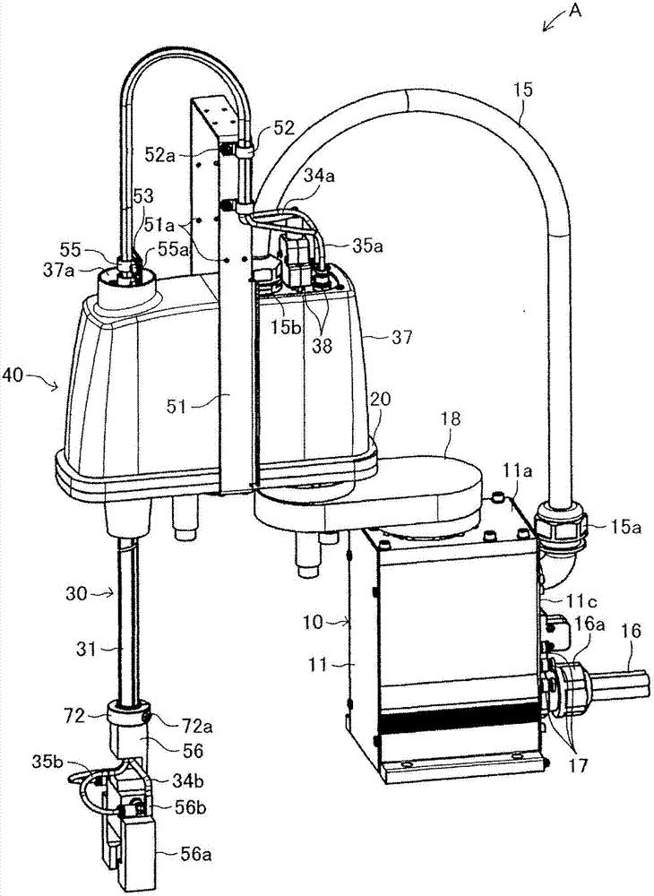
[0031] Hereinafter, the articulated robot according to the first embodiment of the present invention will be described with reference to the drawings. figure 1 and figure 2 The articulated robot A according to this embodiment is shown. The articulated robot A includes a base portion 10 , a first arm 18 , a second arm 20 , a work shaft assembly 30 , and a lift and rotation drive device 40 provided on the second arm 20 to move the work shaft assembly 30 .
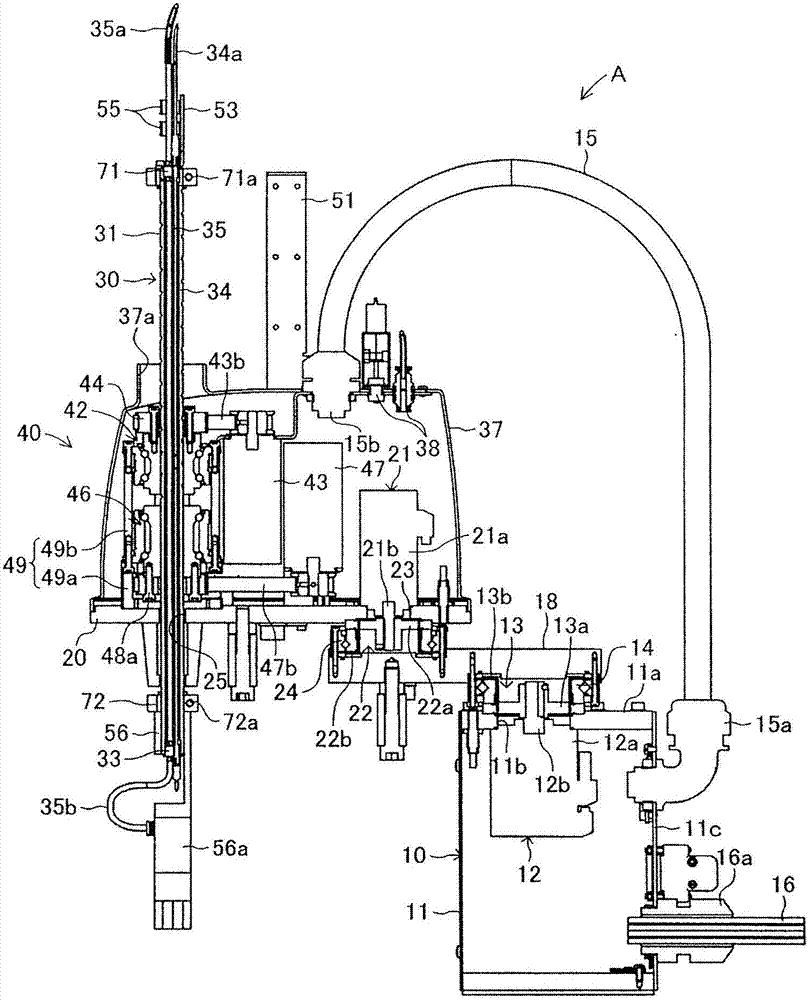
[0032] The base portion 10 is fixedly arranged on the floor, countertop, etc., such as image 3 As shown, it includes: a rectangular box-shaped casing 11 ; a motor 12 fixed to the upper part of the casing 11 ; . In the following description, the up-down direction and the left-right direction are based on image 3 express.
[0033] A hole 11b for attachment is formed in the left side portion of the upper surface portion 11a of the case 11 . The motor 12 and the reduction gear 13 are attached to the upper surface portion...
no. 2 approach )
[0074] Figure 13 and Figure 14 An articulated robot B according to a second embodiment of the present invention is shown.
[0075] In this articulated robot B, instead of the above-mentioned internal piping 35 and external piping 35a, 35b, two connecting pipings 65 (continuous line members) extending continuously are provided, and only the internal wiring 64 is held inside the spindle assembly 60 . The working shaft assembly 60 has a structure in which an upper end connecting member 62 and a lower end connecting member 63 are attached to the upper and lower openings of the hollow working shaft 61, respectively, and an inner portion is connected to the upper end connecting member 62 and the lower end connecting member 63. Wiring 64 (internal line parts). In addition, in the vicinity of the upper end of the working shaft 61 and its side surfaces, such as Figures 15 to 17 As shown, an upper through hole 61a is formed near the lower end of the working shaft 61 and its side ...
PUM
 Abstract
Description
Claims
Application Information
 - R&D
- Intellectual Property
- Life Sciences
- Materials
- Tech Scout
- Unparalleled Data Quality
- Higher Quality Content
- 60% Fewer Hallucinations
Browse by: Latest US Patents, China's latest patents, Technical Efficacy Thesaurus, Application Domain, Technology Topic, Popular Technical Reports.
© 2025 PatSnap. All rights reserved.Legal|Privacy policy|Modern Slavery Act Transparency Statement|Sitemap|About US| Contact US: help@patsnap.com


