Film tearing machine and film tearing method

A film machine and film technology, which is applied in the direction of chemical instruments and methods, layered products, lamination auxiliary operations, etc., can solve the problems that the tape cannot be used again, increase the cost of tearing the polarizer film, etc., and achieve automatic film tearing action, Reduce the cost of tearing film and realize the effect of tearing film action

Inactive Publication Date: 2013-01-30
AU OPTRONICS CORP
View PDF5 Cites 59 Cited by
  • Summary
  • Abstract
  • Description
  • Claims
  • Application Information

AI Technical Summary

Problems solved by technology

However, after each peeling action, the tape cannot be reused
Therefore, using adhesive tape, a non-reusable consumable, to tear the film will increase the cost of tearing the polarizer

Method used


Image

  • Film tearing machine and film tearing method
  • Film tearing machine and film tearing method
  • Film tearing machine and film tearing method

Examples


Embodiment Construction

[0074] The technical solution of the present invention will be described in detail below in conjunction with the accompanying drawings and specific embodiments to further understand the purpose, solution and effect of the present invention, but it is not intended to limit the scope of protection of the appended claims of the present invention.

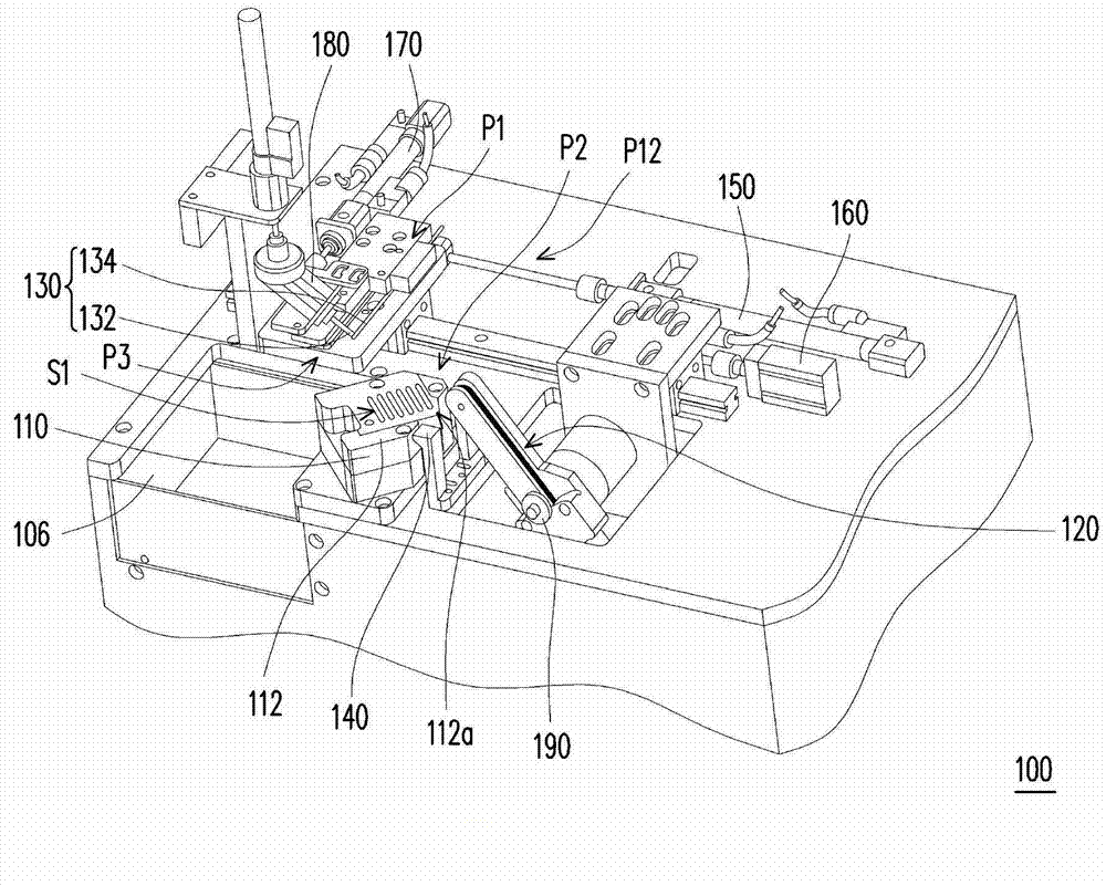
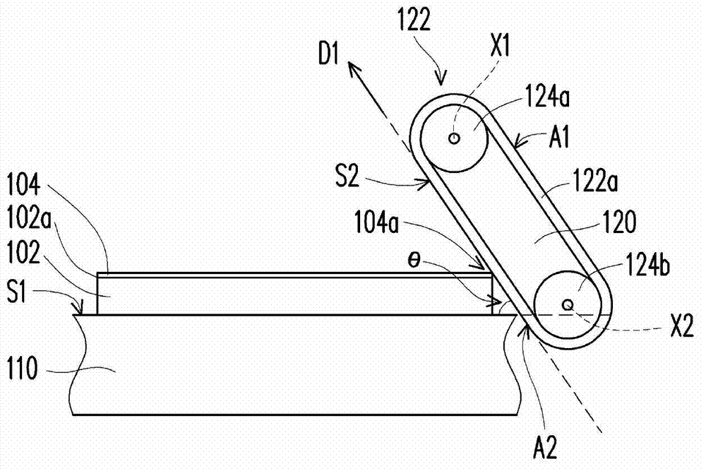
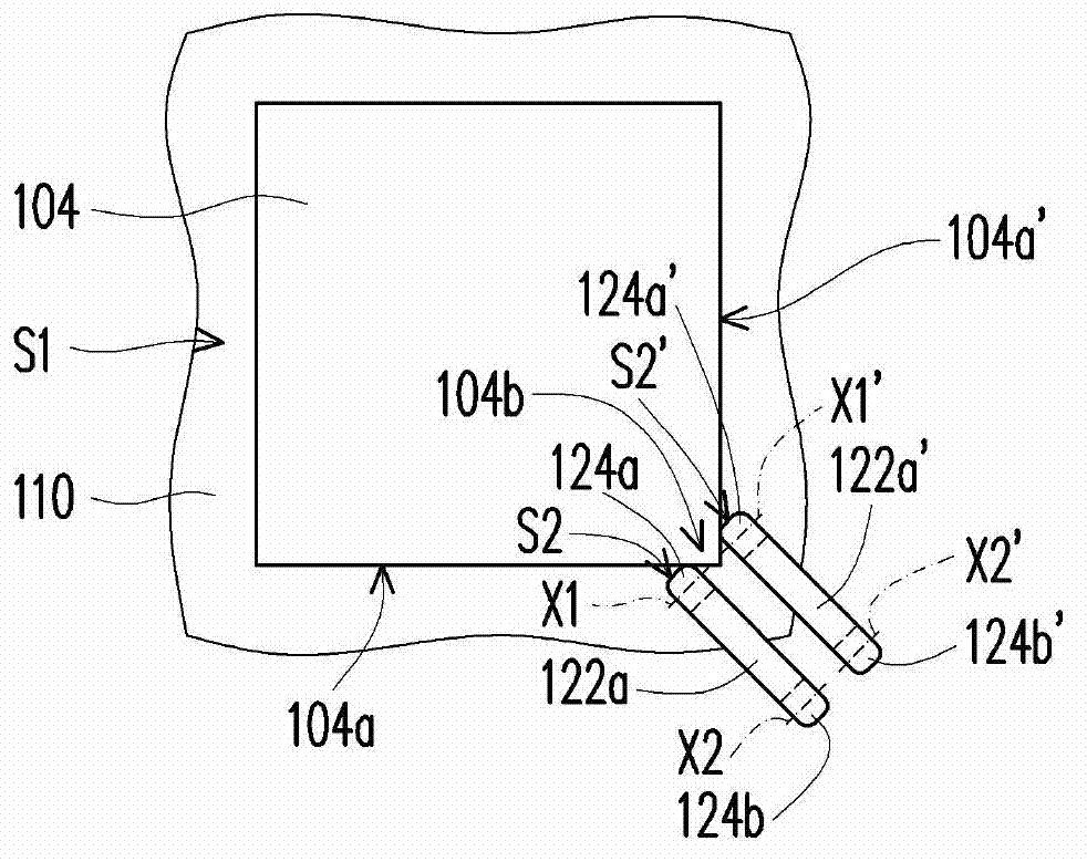
[0075] figure 1 It is a perspective view of a film tearing machine according to an embodiment of the present invention. figure 2 yes figure 1 Schematic diagram of the front view of the tearing device. Please refer to figure 1 and figure 2 , in this embodiment, the film tearing machine 100 includes a carrier 110 , a tearing device 120 and a gripper 130 , adapted to remove the film 104 on the surface 102 a of the substrate 102 . The carrier 110 has a carrying surface S1 for carrying the substrate 102 . In other words, the substrate 102 can be placed on the carrying surface S1 of the carrier 110 so that the film 104 on the surface 10...


PUM

PropertyMeasurementUnit
angleaaaaaaaaaa

Abstract

A film tearing machine is suitable for removing a film on surface of a substrate, and comprises a carrier, a tearing-start device and a clamp, wherein the carrier has a carrier surface for carrying the substrate; the tearing-start device is located at one side of the carrier and has a movable tearing-start element which has a contact surface used for contacting edges of the film; and the clamp is provided with a movable mechanism so that the clamp can move to the upper side of the carrier surface or the clamp moves far away from a bearing surface. The invention further discloses a film tearing method, and according to the method, the film tearing machine is utilized to remove the film on the substrate. The film tearing machine uses actions of the element, instead of using consumables, to remove the film on the substrate, thereby reducing film tearing cost, and automatically tearing the films.

Description

technical field [0001] The present invention relates to a film tearing machine and a film tearing method, and in particular to a film tearing machine and a film tearing method that can automatically tear the film and save costs. Background technique [0002] The liquid crystal display mainly includes a liquid crystal display panel (liquid crystal display panel) and a backlight module (back light module). Wherein, after the liquid crystal display panel is assembled, a polarizer attaching process is performed to attach the polarizer to the liquid crystal display panel. The polarizer can polarize the light source provided by the backlight module, so as to achieve the purpose of controlling the brightness of the liquid crystal display. [0003] Generally speaking, after the polarizer is manufactured, a layer of release film (release film) will be added on the outer layer to protect the adhesive on the polarizer. When the polarizer attaching process is carried out, the release ...

Claims


Application Information

Patent Timeline
Patent Type & Authority Applications(China)
IPC IPC(8): B32B38/10
Inventor 陈明晖王健发赖志明邵明良古清芳
Owner AU OPTRONICS CORP
Why Eureka
Try Eureka