Cascade pump device

A pump device and cascade technology, which is applied to the pump device, the pump, the components of the pumping device for elastic fluid, etc., can solve the problem of increasing the installation space of the cascade pump device, and achieve the effect of restraining the installation space.

Inactive Publication Date: 2013-01-30
NIDEC SANKYO CORP
View PDF9 Cites 2 Cited by
  • Summary
  • Abstract
  • Description
  • Claims
  • Application Information

AI Technical Summary

Problems solved by technology

Therefore, there is a problem that the installa

Method used


Image

  • Cascade pump device
  • Cascade pump device
  • Cascade pump device

Examples


Example

[0215] (Other implementations)

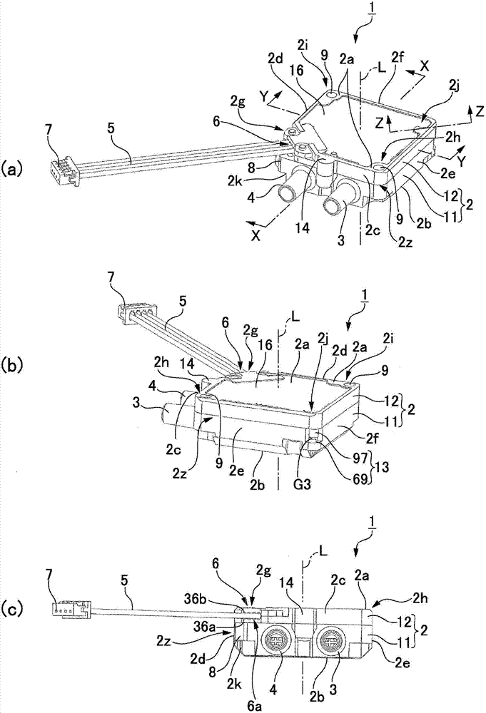
[0216] In the above example, the pump casing 2 has a square prism shape, but the pump casing 2 can also be formed in a cylindrical shape, a triangular prism shape, a pentagonal prism shape, a hexagonal prism shape, or a polygonal prism shape. Even in the case of the above-mentioned shape, if the suction pipe and discharge pipe extending in the same direction parallel to each other, and the wire extraction part are provided between the two end faces located at both ends of the pump casing in the axial direction, the wire extraction guide If the angle formed by the leading direction D1 of the part and the protruding direction of the suction pipe and the discharge pipe is less than 90°, when the cascade pump unit is installed on an external device, the suction pipe and the discharge pipe can protrude on the side of the pump casing. Provide a space for routing piping such as hoses connected to the suction pipe and discharge pipe, and a space for ro...


PUM


Abstract

Provided is a cascade pump device which can reduce installation space. The cascade pump device (1) may include a pump chamber (25), an impeller (21), a magnetic drive mechanism structured to rotate a coil (27), and a pump case (2) installed with the above components. The pump case (2) is provided with two end faces (2a,2b) located at both ends in an axial line direction and an intermediate part (2z) between the two end faces. The intermediate part (2z) is provided with a suction pipe (3) and a discharge pipe (4) and a wiring outlet part (6) for taking out wiring lines (5) for supplying an exciting current to a drive coil of a motor. The suction pipe and the discharge pipe are protruded in the same direction and the wiring outlet part is provided with a wiring line drawing-out guide part (6a) which determines a drawing-out direction (D1) of the wiring lines to the outer side. An angle between the drawing-out direction (D1) and a protruding direction of the suction pipe and the discharge pipe is less than 90 DEG around the axial line.

Description

technical field [0001] The present invention relates to a cascade pump device with a structure in which a suction pipe and a discharge pipe communicated with a pump chamber protrude parallel to each other from the side of a pump casing. Background technique [0002] A cascade pump device for pressurized liquid transfer called a vortex pump or a cascade pump is described in Patent Document 1. The cascade pump device of the above document includes a pump chamber, an impeller, a magnetic drive mechanism that drives the impeller to rotate by exciting a drive coil, and a pump housing in which they are installed. The pump casing has a flat cylindrical shape, and a suction pipe and a discharge pipe communicating with the pump chamber protrude parallel to each other from the side of the pump casing. In the above document, the magnetic drive mechanism is a motor, and a cable for supplying an exciting current to a drive coil of the motor is drawn out radially outward from the lower e...

Claims


Application Information

Patent Timeline
IPC IPC(8): F04D29/40F04D29/00
CPCF04D29/00F04D5/006F04D29/40F04D13/0673F04D13/0693
Inventor 横沢满雄鲇泽优
Owner NIDEC SANKYO CORP
Why Eureka
Try Eureka