Test experiment system for revolving speed and pressure property of hydraulic transformer

A technology for hydraulic transformers and testing experiments, which is applied in the testing of fluid pressure actuation systems, fluid pressure converters, fluid pressure actuation devices, etc., to achieve the effects of simple structure, simple and convenient operation, and high experimental efficiency.

Inactive Publication Date: 2013-01-30
HARBIN INST OF TECH
View PDF5 Cites 7 Cited by
  • Summary
  • Abstract
  • Description
  • Claims
  • Application Information

AI Technical Summary

Problems solved by technology

[0005] In order to solve the problem that there is no testing system capable of testing the rotational speed and pressure performance of hydraulic transformers, the present invention further proposes a hydraulic transformer rotational speed and pressure performance testing experimental system

Method used


Image

  • Test experiment system for revolving speed and pressure property of hydraulic transformer

Examples


specific Embodiment approach 1

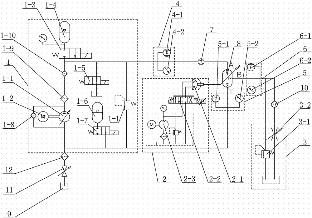
[0009] Specific implementation mode 1: Combination figure 1 To explain this embodiment, the hydraulic transformer speed and pressure performance test experiment system described in this embodiment includes a hydraulic constant pressure network component 1, a control component 2, a simulated load component 3, a high pressure end A port pressure monitoring component 4, a low pressure end T port pressure monitoring component 5, load port B port pressure monitoring component 6, A port flow sensor 7, oil tank 9 and B port flow sensor 10, the oil outlet of oil tank 9 is connected to hydraulic constant pressure network component 1, and the inlet of oil tank 9 The oil port is connected to the oil outlet of the hydraulic transformer 8, the constant pressure output end of the hydraulic constant pressure network component 1 is connected to the high pressure end A of the hydraulic transformer 8, the control component 2 is connected to the hydraulic transformer 8, and the load output port of...

specific Embodiment approach 2

[0011] Specific implementation manner two: combination figure 1 To explain this embodiment, the hydraulic constant pressure network component 1 of the test system for testing the speed and pressure performance of the hydraulic transformer in this embodiment includes a constant pressure variable pump 1-1, an electric motor 1-2, and two-position two-way electromagnetic commutation Valve 1-3, high-pressure hydraulic accumulator 1-4, first two-position two-way reversing valve 1-5, low-pressure hydraulic accumulator 1-6 and second two-position two-way reversing valve 1-7, electric motor 1-2 is connected to the constant pressure variable pump 1-1, the oil inlet of the constant pressure variable pump 1-1 is connected to the oil outlet of the oil tank 9, and the oil outlet of the constant pressure variable pump 1-1 is the high pressure end of the hydraulic transformer 8. Port A connection, the high-pressure hydraulic accumulator 1-4 is set in the pipeline between the outlet port of the...

specific Embodiment approach 3

[0014] Specific implementation mode three: combination figure 1 To explain this embodiment, the first check valve 1-8 is provided between the oil inlet and the oil outlet of the constant pressure variable pump 1-1 of the hydraulic transformer speed and pressure performance test experiment system in this embodiment. , The oil outlet of the constant pressure variable pump 1-1 is provided with an outlet filter 1-9. Other components and connection relationships are the same as in the second embodiment.


PUM


Abstract

The invention relates to a test experiment system, and particularly relates to a test experiment system for the revolving speed and the pressure property of a hydraulic transformer, the system is used for solving the problem that the revolving speed and pressure property of the hydraulic transformer can not be measured yet by the test experiment system at present. The test experiment system is characterized in that the constant pressure output end of a hydraulic constant pressure network assembly is communicated with the high-pressure end A port of the hydraulic transformer; a control assembly is connected with the hydraulic transformer; the load output end of an artificial load assembly is communicated with the load end B port of the hydraulic transformer; a high-pressure end A port pressure monitoring assembly is connected with the high-pressure end A port of the hydraulic transformer; a load end B port pressure monitoring assembly is connected with the load end B port of the hydraulic transformer; an A port flow sensor is connected with the high-pressure end A port of the hydraulic transformer; and a B port flow sensor is connected with the load end B port of the hydraulic transformer. The test experiment system disclosed by the invention is used for the property test of the hydraulic transformer.

Description

Technical field [0001] The invention relates to a testing experiment system, in particular to a testing experiment system for the rotational speed and pressure performance of a hydraulic transformer. Background technique [0002] The hydraulic system has been applied to many occasions due to its high power density, but the hydraulic system also has the shortcoming of low efficiency. Under the increasing energy crisis, the energy saving research of the hydraulic system is becoming a hot spot for the majority of scientific researchers. . [0003] The secondary regulation technology based on the constant pressure network realizes the volume control of the actuators without throttling loss, improves the system efficiency, and can recover and reuse the energy of the load. Although the secondary adjustment hydrostatic transmission system has been widely used in many industries, the working principle of the secondary adjustment hydrostatic transmission system determines that its actuator...

Claims


Application Information

Patent Timeline
Patent Type & Authority Applications(China)
IPC IPC(8): F15B19/00F15B3/00
Inventor 姜继海刘成强高丽新杨冠中沈伟张翼鹏
Owner HARBIN INST OF TECH
Why Eureka
Try Eureka