Combined locking device

A locking device and locking technology, applied in transmission parts, connecting components, belts/chains/gears, etc., can solve problems such as failure to meet locking requirements, loose locking devices, etc., and achieve easy structural design and reduced size , The effect of reducing manufacturing costs

Inactive Publication Date: 2013-01-30
CHINA NORTH VEHICLE RES INST
View PDF6 Cites 4 Cited by
  • Summary
  • Abstract
  • Description
  • Claims
  • Application Information

AI Technical Summary

Problems solved by technology

Under the action of inertial force, the early locking devic

Method used


Image

  • Combined locking device
  • Combined locking device

Examples


Embodiment Construction

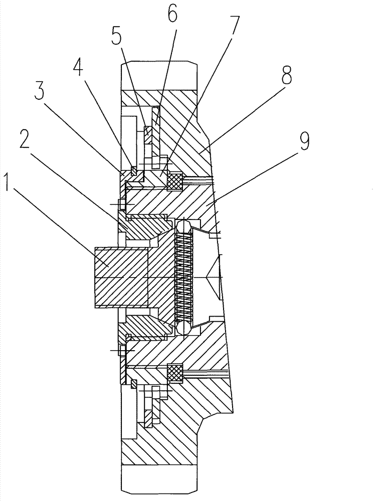
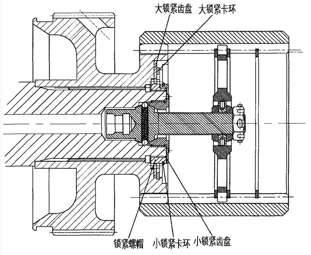
[0008] A combined locking device provided by the present invention will be further described below in conjunction with the accompanying drawings.

[0009] The present invention is a new combined locking device for the reducer and the transmission. During the braking process of the reducer and the transmission, it is necessary to ensure that the inner hub of the brake (arc gear of the reducer) does not move in the axial position Therefore, the axial position of the circular arc gear 8 must be fixed, wherein the internal splines of the circular arc gear 8 of the reducer and transmission structure mesh with the external splines of the input gear 9, and the teeth of the circular arc gear 8 and the center shaft There are grooves suitable for accommodating the components of the combined locking device between the positions; the external thread of the ball bearing seat 2 cooperates with the internal thread of the input shaft of the reducer and the transmission (the input shaft where t...


PUM


Abstract

The invention belongs to a locking device, in particular to a combined locking device used for a planetary redactor and a speed changer, aiming to provide an effective locking device for preventing a rotating piece from axially moving, which can be used for not only effectively limiting the axial movement of the rotating piece, but also meeting requirement on compactedness. The combined locking device comprises a locking screw cap, a large locking fluted disc, a large locking clamp ring, a small locking fluted disc and a small locking clamp ring, wherein inner teeth of the large locking fluted disc and outer teeth of the locking screw cap are engaged; the large locking clamp ring is arranged in a slot of a circular tooth gear to press the large locking fluted disc; the rotation of the locking screw cap is limited by the large locking clamp ring and the large locking fluted disc so as to effectively prevent the locking screw cap from loosing; an outer thread of a ball bearing block and an inner thread of an input shaft are matched so as to limit the axial movement of a tool bolt; inner teeth of the small locking fluted disc and outer teeth of the ball bearing block are engaged; and the small locking clamp ring is arranged in a slot of the small locking clamp ring and the locking screw cap so as to limit the rotation of the ball bearing block.

Description

technical field [0001] The invention belongs to the technical field of locking devices, and in particular relates to a novel combined locking device used for speed reducers and transmissions. Background technique [0002] With the advancement of technology, the speed of planetary reducers and transmissions is gradually increasing, and their structures are becoming more and more compact. Some rotating parts need to limit axial movement, otherwise they will cause failure. For example, during the braking process, it is necessary to ensure that the inner hub of the brake (the arc gear of the reducer) does not move in the axial position, otherwise the wear of the friction plate will be aggravated. Therefore, the axial position of the arc gear must be fixed to prevent The arc gear moves axially, otherwise it will affect the performance of the whole vehicle. Under the action of inertial force, the early locking devices tend to loosen and fail to meet the locking requirements. Co...

Claims


Application Information

Patent Timeline
IPC IPC(8): F16B21/10F16H57/00
Inventor 潜波李洪武周广明吕庆军石岳江赵欣源张鹤许晋邢庆坤李慎龙程燕尹华兵
Owner CHINA NORTH VEHICLE RES INST
Why Eureka
Try Eureka