Bullet puller of large-caliber machine gun bullet

A large-caliber, bullet-puller technology, which is applied to grapple hooks, weapon accessories, offensive equipment, etc., can solve the problem of inability to meet the clamping force of large-caliber bullets, and achieve the effects of simple structure, low cost, and convenient operation.

Inactive Publication Date: 2013-01-30
ZHONGBEI UNIV
View PDF6 Cites 78 Cited by
  • Summary
  • Abstract
  • Description
  • Claims
  • Application Information

AI Technical Summary

Problems solved by technology

Although a domestic journal mentioned a simple device specially used to disassemble bullets, the bullet head and bullet tail in this device are only clamped by the tightening force of small screws, and its clamping force is too small to be used for Decomposing small-caliber bullets with a diameter of less than 10mm cannot meet the clamping force required for disassembling large-caliber bullets
Although many bullet production factories have special large-scale automatic disintegrating bullet machines for measuring and pulling out elastic force, which can be used to disintegrate bullets, but for scientific research institutions and relevant departments with very little demand, large-scale disintegrating bullet machines are not necessary. A simple and safe device that can separate large-caliber machine gun bullets is needed

Method used


Image

  • Bullet puller of large-caliber machine gun bullet
  • Bullet puller of large-caliber machine gun bullet
  • Bullet puller of large-caliber machine gun bullet

Examples


Embodiment Construction

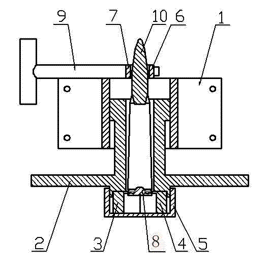
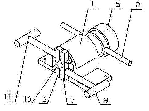
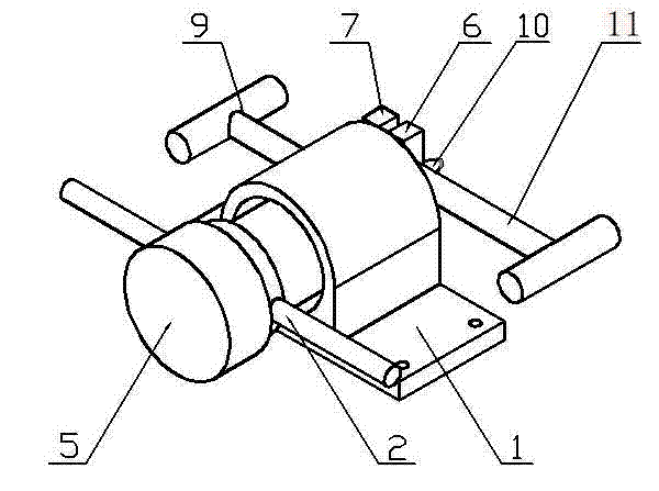
[0012] The outer diameter of the head of the pulling screw 2 is milled with a 20mm long thread to cooperate with the thread of the base. The inside of the pulling screw 2 is milled with a through hole with an inner diameter of 26mm that runs through the head and tail to ensure that the bullet is inserted smoothly. The rear end of the pulling screw rod 2 is milled with an inner hole with a diameter of 50 mm and a height of 5 mm to ensure that the left locking flap 3 and the right locking flap 4 can be smoothly put into the pulling screw rod 2 and positioned. Pulling screw rod 2 afterbody outer diameters are milled with thread, and use with the internal thread of protective cover 5. The left flap 3 and the right flap 4 are two symmetrical semicircular flaps with a height of 20mm and an outer diameter of 49mm. A semicircular hole with a height of 18.5mm and a diameter of 30mm is milled in the middle of each flap. The mm diameter is slightly larger than the semicircular hole of th...


PUM


Abstract

The invention discloses a bullet puller of a large-caliber machine gun bullet. The bullet puller comprises a base, a bullet pulling screw, snapping clacks, a protection cover, clamping heads and tightening screws; a thread through hole is arranged in the middle of the base, and two rods are welded at the tail of the bullet pulling screw; a left snapping clack and a right snapping clack are two symmetrical semicircle snapping clacks, and a semicircle positioning hole is milled in the middle of each snapping clack; a left clamping head and a right clamping head are cuboid blocks in same structures, semicircle grooves which are matched with the bullet are milled along the height direction of the left clamping head and the right clamping head, a chamfer is arranged at the contact position of the bullet, and the surface of the chamfer is subjected to surface engraving processing; a through hole and a thread hole are milled at positions of two sides in the width direction respectively; and a left tightening screw penetrates through a through hole of the left clamping head and then is screwed into the thread hole of the right clamping head, the right tightening screw penetrates through the through hole of the right clamping head and then is screwed into the thread hole of the left clamping head, the grooves of the left clamping head and the right clamping head oppositely form a closed frame, and the grooves are aligned to a cylindrical portion of the bullet. The bullet puller is simple in structure, safe, convenient and capable of separating a bullet head from a bullet shell of the large-caliber machine gun bullet.

Description

technical field [0001] The invention relates to a simple, safe and efficient professional device capable of separating the warhead and shell case of machine gun bullets. The device can safely decompose large-caliber machine gun bullets with bullet diameters ranging from 10mm to 16mm. Background technique [0002] In some experimental and research situations, it is necessary to experiment with large-caliber machine gun bullets of different warhead shapes under the same caliber and the warhead needs to be replaced. In some cases, it is necessary to disassemble and destroy dud bombs. The warhead is separated from the shell case. Although a domestic journal mentioned a simple device specially used to disassemble bullets, the bullet head and bullet tail in this device are only clamped by the tightening force of small screws, and its clamping force is too small to be used for Disintegrating small-caliber bullets with a diameter of less than 10mm cannot meet the clamping force re...

Claims


Application Information

Patent Timeline
Patent Type & Authority Applications(China)
IPC IPC(8): F41A15/00
Inventor 宋河金王金虎杨光晖王鹏飞刘恒著
Owner ZHONGBEI UNIV
Why Eureka
Try Eureka