
Ferrofluid optical current sensor with horizontal bias device and method

A ferrofluid, bias device technology, applied in the direction of measurement device, measurement of current/voltage, measurement of electrical variables, etc., can solve the problems of long response time, long relaxation time, low sensitivity and accuracy of non-constant current, etc. Achieve the effect of shortening response time, enhancing sensitivity, and optimizing dynamic characteristics

Inactive Publication Date: 2013-01-30
STATE GRID CHONGQING ELECTRIC POWER +1
View PDF3 Cites 3 Cited by
  • Summary
  • Abstract
  • Description
  • Claims
  • Application Information

AI Technical Summary

Problems solved by technology

[0003] The main disadvantages of existing ferrofluid optical current sensing methods are long response time, low sensitivity and low accuracy of non-constant current
The above defects are caused by the long relaxation time of the magnetic moment of the magnetic particles and the orientation of the external field when the ferrofluid is magnetized by an external magnetic field.

Method used


Image

  • Ferrofluid optical current sensor with horizontal bias device and method
  • Ferrofluid optical current sensor with horizontal bias device and method
  • Ferrofluid optical current sensor with horizontal bias device and method

Examples


Embodiment Construction

[0032] Hereinafter, preferred embodiments of the present invention will be described in detail with reference to the accompanying drawings. It should be understood that the preferred embodiments are only for illustrating the present invention, but not for limiting the protection scope of the present invention.

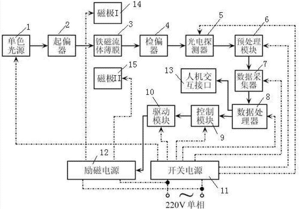
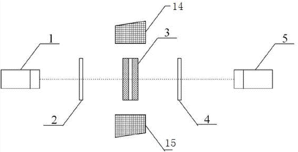
[0033] Such as figure 1 and figure 2 As shown, the ferrofluid optical current sensing device with a lateral bias device of the present invention includes a monochromatic light source 1, a polarizer 2, a ferrofluid thin film 3, an analyzer 4, a photodetector 5, Preprocessing module 6, data collector 7, data processor 8, control module 9, drive module 10, switching power supply 11, excitation power supply 12, man-machine interaction interface 13, magnetic pole I14 and magnetic pole II15;

[0034] The surface of the ferrofluid film 3 is kept perpendicular to the magnetic field generated by the current to be measured or the direction of the magnetic field to be measured...


PUM


Abstract

The invention discloses a ferrofluid optical current sensor with a horizontal bias device. The ferrofluid optical current sensor comprises a monochromatic source, a polarizer, a ferrofluid film, a polarization analyzer and a photoelectric detector; in addition, a horizontal bias magnetic field generator is arranged in the ferrofluid optical current sensor; during use, monochromatic beams become linearly polarized light through the polarizer, the linearly polarized light which is transmitted in the ferrofluid film is rotated at a certain angle through the ferrofluid film under the modulating action of an externally applied longitudinal magnetic field, and the rotation angle is related to the strength of the externally applied longitudinal magnetic field, so the magnitude of the current for generating the externally applied longitudinal magnetic field can be obtained by detecting the rotation angle of the linearly polarized light, the magnetic moment turning speed of magnetic particles can be improved through a magnetic field generated by the horizontal bias magnetic field generator when the magnetic particles in the ferrofluid are modulated by the externally applied longitudinal magnetic field, the response time is shortened, and the sensitivity and the accuracy of the sensor are improved; and based on the sensor, the invention also discloses a current measuring method.

Description

technical field [0001] The invention relates to a ferrofluid optical current sensing device with a lateral bias device. The invention also uses the ferrofluid optical current sensing device to realize a ferrofluid optical current sensing device that can improve the ferrofluid optical current sensing device. The performance of the current sensor and the method to achieve the purpose of current detection. Background technique [0002] The basic principle of the ferrofluid optical current measurement method is the longitudinal magneto-optical rotation effect of the ferrofluid, that is, when the monochromatic polarized beam passes through the ferrofluid modulated by the longitudinal magnetic field, the vibration direction of the polarized light will rotate, and the rotation angle The magnitude of is related to the strength of the modulating magnetic field, so the strength of the modulating magnetic field can be deduced by measuring the rotation angle of the polarized light vibra...

Claims


Application Information

Patent Timeline
Patent Type & Authority Applications(China)
IPC IPC(8): G01R19/00
Inventor 王士彬叶鹏王华唐彬杜娟刁晓波曹霞全红
Owner STATE GRID CHONGQING ELECTRIC POWER
Learn More