Fixing device for placards

A technology for fixing devices and placards, which is applied to display devices, markings, instruments, etc., can solve the problems of troublesome, unsightly, and enterprise expenses for construction workers, and achieve the effect of convenient disassembly, firm and beautiful fixation

Active Publication Date: 2015-03-11
HEILONGJIANG THIRD ELECTRIC POWER CONSTR CO LTD OF CHINA ENERGY ENG GRP
View PDF14 Cites 0 Cited by
  • Summary
  • Abstract
  • Description
  • Claims
  • Application Information

AI Technical Summary

Problems solved by technology

[0002] At present, the general placard fixing is to select the position to be fixed, and then weld the embedded bolts or drill holes with an impact drill to install expansion bolts on the steel column or concrete column that needs to be fixed, and then fasten the placard with nuts; Some of them are nailed with a nail gun or fixed with stainless steel nails with a hammer; some are even tied directly to the steel column with wire, which is unsightly and unsafe
The above-mentioned methods need to use a lot of professional tools, such as impact drills, nail guns, etc., which bring troubles to the construction personnel, reduce labor efficiency, and bring unnecessary expenses to the enterprise.

Method used


Image

  • Fixing device for placards
  • Fixing device for placards
  • Fixing device for placards

Examples


Embodiment 1

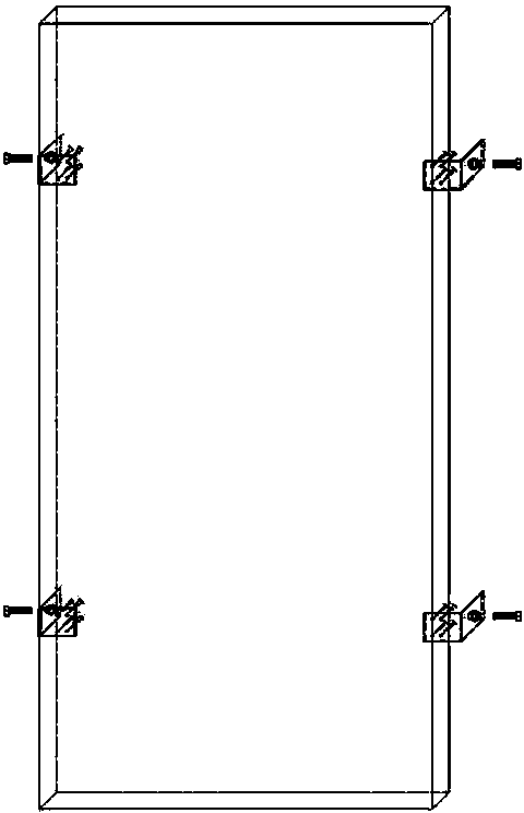
[0022] Step 1: Measure the width of the concrete and steel columns that need to be fixed on site, and make signs with appropriate widths. The steel and concrete columns on site generally have a width of 0.5-0.8 meters, which is just right for hanging signs.

[0023] The second step: intercept as Figure 5 A piece of L40*40*5 angle iron, in Figure 5 Open holes at the appropriate positions as shown, 4 φ3 self-tapping screw holes, 1 φ10.5 screw hole, align the center on the outside of the screw hole, and spot weld one Figure 5 M10 nuts shown, combined into Figure 6 Assemblies shown.

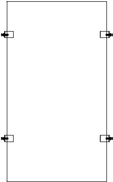
[0024] Step 3: Retrieve the placard, use Figure 7 Self-tapping handles shown Figure 6 Assemblies shown in sets of four, in figure 1 and figure 2 , image 3 , Figure 4 Just tighten the four corners as shown.

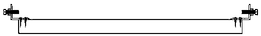
[0025] Step 4: Take the placard to the scene, choose an appropriate height, place the placard, and use Figure 7 Adjust the stress of the bolts shown as jacking wires, so that ...

Embodiment 2

[0031] The first step: same as embodiment 1;

[0032] The second step: intercept as Figure 5 A piece of L40*40*5 angle iron, in Figure 5 Holes are drilled at the appropriate positions as shown, 4 holes for φ3 self-tapping screws and 1 hole for φ10.5 screws.

[0033] The 3rd step: identical with embodiment 1;

[0034] Step 4: Take the placard to the site, choose an appropriate height, and place the placard; if the unit does not have welding conditions, install it in the order of bolts, angle irons, and nuts. The nuts are on the inside of the angle irons, and hold the nuts with a thin wrench Without turning, another wrench turns the bolt to make a fixed installation. Adjust its force so that the placard is fixed on the edge of the concrete column and steel column, and the fixing effect can also be achieved.


PUM


Abstract

A fixing device for placards can be mounted and fixed fast and conveniently. Hold-type fixing is used. The fixing device for placards comprises a placard, angle irons, nuts, bolts and self-tapping screws. The angle irons and the nuts are integrally combined and fixedly connected with the placard through the self-tapping screws. The bolts are screwed into threaded holes of the angle irons and abutted against outer surfaces, provided with vertical edges, of buildings, steel-structured columns and the like. The placard is stressed by tightening the bolts. The placard can be fixed and prevented from falling as long as self weight of the placard cannot overcome friction force between the bolts and the surfaces of the buildings and steel-structured columns. The fixing device for placards is low in manufacturing cost and timesaving and laborsaving, is made by slightly processing common angle irons on site, and can be mounted with a screwdriver and a wrench.

Description

Technical field [0001] The invention relates to a placard fixing device on the construction site, especially for the place where the steel structure of the boiler is not allowed to be welded and the wall surface is not allowed to be damaged on the concrete pillars, but the placards need to be installed for the needs of safe and civilized construction. The utility model relates to a fixing device which is convenient for fixing and dismounting. Background technique [0002] At present, the general placard fixing is to select the position to be fixed, and then weld the embedded bolts or drill holes with an impact drill to install expansion bolts on the steel column or concrete column that needs to be fixed, and then fasten the placard with nuts; Some of them are nailed with a nail gun or fixed with stainless steel nails with a hammer; some are even tied directly to steel columns with iron wires, which is unsightly and unsafe. The above methods require the use of many professio...

Claims


Application Information

Patent Timeline
Patent Type & Authority Patents(China)
IPC IPC(8): G09F7/18
Inventor 李安华张途晟刘晓斌张美玲张歆炜
Owner HEILONGJIANG THIRD ELECTRIC POWER CONSTR CO LTD OF CHINA ENERGY ENG GRP
Why Eureka
Try Eureka