Magnetomotive device and using method thereof

A magnetic power and magnetic pole technology, applied in the directions of generators/motors, electrical components, etc., can solve the problems of low output power, insufficient magnetic power, uneven power, etc., and achieve high output power, increase output power, and improve power output. Effect

Active Publication Date: 2013-01-30
SUIZHOU SHUANGYI LONGJI MACHINERY TECH
View PDF5 Cites 3 Cited by
  • Summary
  • Abstract
  • Description
  • Claims
  • Application Information

AI Technical Summary

Problems solved by technology

[0006] The purpose of the present invention is to overcome the problems of insufficient magnetic power, small output power and uneven power in the prior art, and provide a magnetic power device with sufficient magnetic power, large output power, uniform and coherent power and its use method

Method used


Image

  • Magnetomotive device and using method thereof
  • Magnetomotive device and using method thereof
  • Magnetomotive device and using method thereof

Examples


Embodiment 1

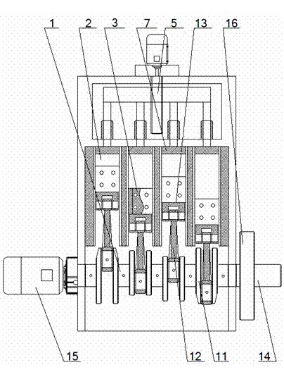
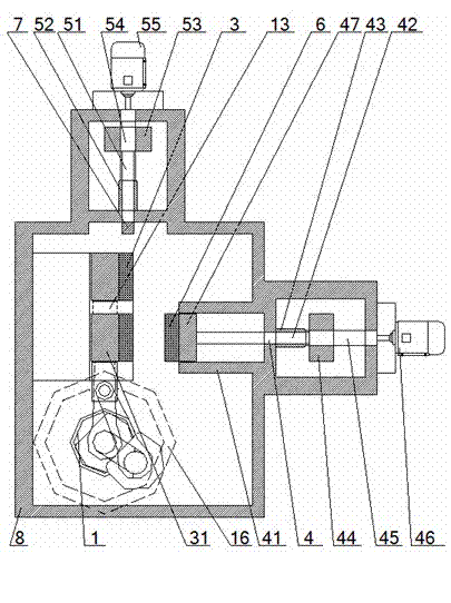
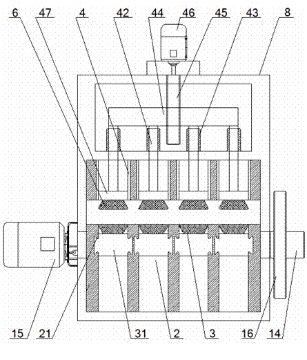
[0115] A kind of magnetodynamic device, comprises crankshaft 1, main motor 15, back adjustment device 4, top adjustment device 5 and four magnetodynamic units, the input shaft of described crankshaft 1 is connected with the output shaft of main motor 15, the crankshaft 1 The output shaft is connected with the power output shaft 14 through the flywheel 16; the magnetic power unit includes a sliding permanent magnet 3, a back permanent magnet 6 and a top permanent magnet 7, and the sliding permanent magnet 3 is consistent with the shape of the back permanent magnet 6, and The cross-sections of the sliding permanent magnet 3 and the back permanent magnet 6 are isosceles trapezoidal, the front of the sliding permanent magnet 3 is fixedly connected to the back of the slider 31, and the two sides of the slider 31 are connected to the guide grooves 21 set on the inner sides of the guide channel 2. Sliding fit, the bottom of the slider 31 is connected with one end of the crankshaft con...


PUM


Abstract

The invention relates to a magnetomotive device, which comprises a crankshaft, a main motor and at least two magnetomotive units, wherein an output shaft of the main motor is connected with a power output shaft sequentially through the camshaft and a flywheel; a sliding permanent magnet in each magnetomotive unit is connected with a rod journal on the crankshaft through a crankshaft connecting rod; a back permanent magnet which corresponds to each sliding permanent magnet is arranged right behind a leading channel where each sliding permanent magnet is located; and a top permanent magnet is correspondingly arranged above each sliding permanent magnet. When the magnetomotive device is used, the repulsive force exists between the sliding permanent magnets and the back permanent magnets to facilitate the sliding permanent magnets to drive the crankshaft to rotate in an accelerative manner through the crankshaft connecting rod. The magnetomotive device disclosed by the invention has the advantages of sufficient magnetomotive power, large output power, uniform and coherent power output and high stability.

Description

technical field [0001] The invention relates to a device for increasing power output by utilizing magnetic energy, in particular to a magnetic power device and a method for using the same, which is particularly suitable for improving the uniformity and consistency of output power and power output. Background technique [0002] Permanent magnets have the characteristics of same-sex repulsion and opposite-sex attraction. When two bar-shaped magnets of the same size and equal magnetic force are placed opposite each other with the poles of the same name pointing in the same direction and parallel to each other, the distance between the two magnets is reduced, and the two The repulsive force between the magnets will cause the two magnets to stagger. [0003] The Chinese patent publication number is CN101552578A, and the publication date is October 7, 2009. The invention patent discloses a device for converting magnetic energy into mechanical energy, including a frame, a cylinder ...

Claims


Application Information

Patent Timeline
Patent Type & Authority Applications(China)
IPC IPC(8): H02N11/00
Inventor 李逵
Owner SUIZHOU SHUANGYI LONGJI MACHINERY TECH
Why Eureka
Try Eureka