Auxiliary method for tracking suspicious people by monitoring system

A monitoring system and auxiliary tracking technology, applied in the direction of closed-circuit television system, digital output to display equipment, etc., to achieve the effects of high tracking accuracy, simple implementation method and fast tracking speed

Inactive Publication Date: 2013-01-30
BEIJING AEROSPACE FUDAO HIGH TECH
5 Cites 18 Cited by

AI-Extracted Technical Summary

Problems solved by technology

[0004] In order to solve the problem of continuous and rapid tracking of suspicious personnel, the pre...

Method used

The difference of the auxiliary tracking method realized by the present invention is that it realizes the multi-point continuous auxiliary tracking function in the building, combines the spatial information and the video surveillance system, and through simple visual operation, it can quickly Switching to the monitoring screen of the monitoring point where the susp...

Abstract

The invention discloses an auxiliary method for tracking suspicious people by a monitoring system. The method comprises the following steps of: configuring the attribute of a monitoring point, modeling a monitored picture and switching the monitored picture. An auxiliary function for continuously tracking a plurality of points in a building is realized; space information and a video monitoring system are combined, so that the video monitoring system can be quickly switched to the monitored picture of a monitoring point at which a suspicious personnel is positioned through simple visible operation; the tracking speed is high; the tracking precision is high; and the implementation method is simple.

Application Domain

Technology Topic

Image

  • Auxiliary method for tracking suspicious people by monitoring system
  • Auxiliary method for tracking suspicious people by monitoring system
  • Auxiliary method for tracking suspicious people by monitoring system

Examples

  • Experimental program(1)

Example Embodiment

[0031] The present invention will be described in detail below with reference to the drawings and embodiments.
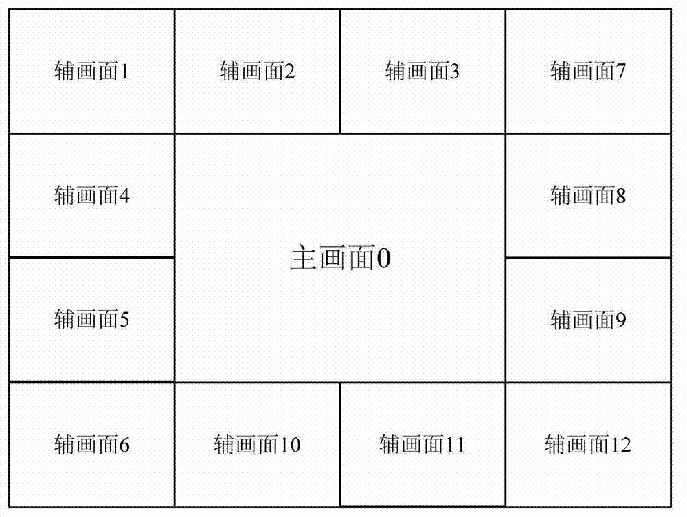
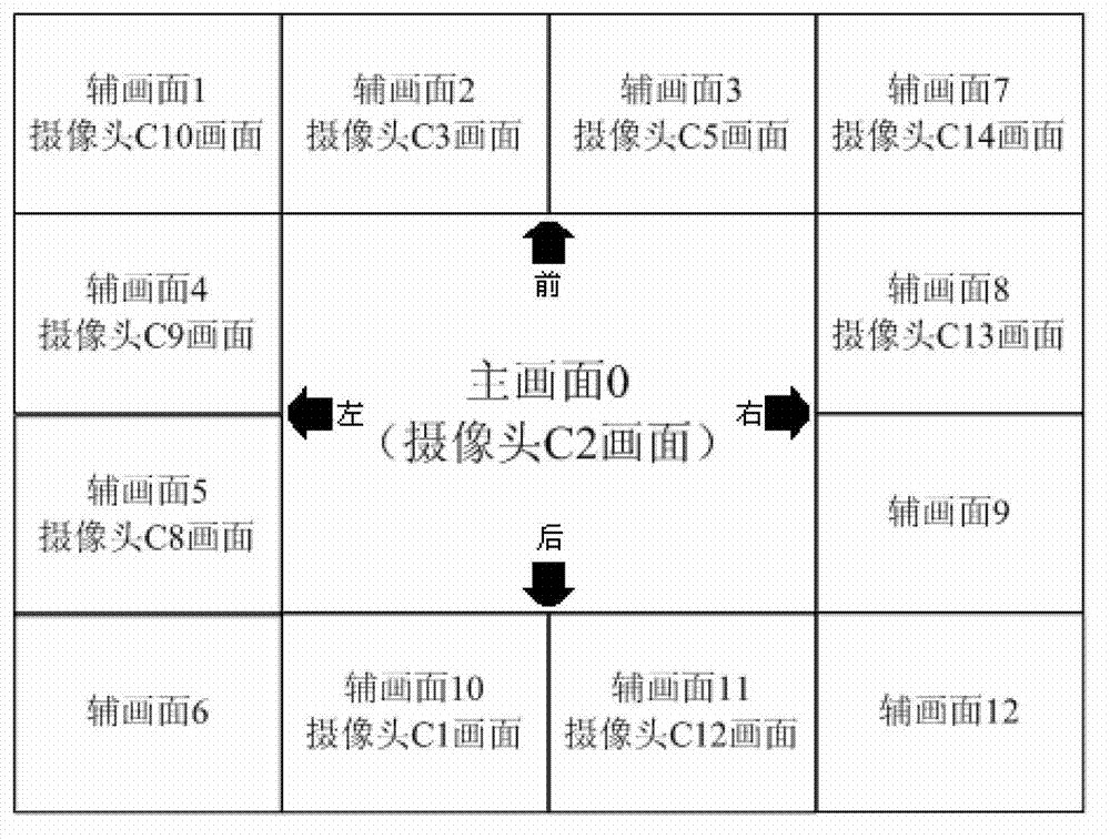
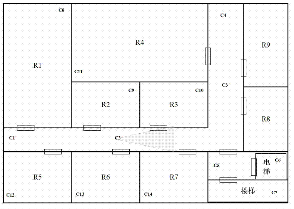
[0032] The invention relates to an auxiliary tracking method for suspicious persons in a monitoring system. The idea of ​​the method is to establish a monitoring interface by modeling all reachable monitoring points in a building on a monitoring seat computer in the monitoring system. The main screen is divided into the main screen and the auxiliary screen. The main screen displays the location of the monitoring point where the suspicious person is currently located. The auxiliary screen displays all the steps of the main screen to the location of the monitoring point. Click any auxiliary screen in the monitoring screen to The screen is switched to this screen, and the auxiliary screen is correspondingly switched to the monitoring screen where all steps of this screen can reach the monitoring point. The monitoring personnel can quickly capture the current state of the suspicious person and the path that may be taken in the next step by switching between the main and the auxiliary.
[0033] This method is specifically implemented through the following steps:
[0034] (1) In the seat computer, configure the attributes of the monitoring points and store them in the database.
[0035] Monitoring point attribute configuration includes configuring the basic attributes, position and direction attributes, floor attributes, and neighboring point attributes of each monitoring point camera. Among them, the basic attributes include the name of the monitoring point, IP address, port number, etc.; the location attribute is that the surveillance camera uses a reference point (any point in space) as the origin, the east direction is the x axis, the north direction is the y axis, and the sky direction is z The coordinates in the coordinate system of the axis; the direction attribute is the angle between the camera's direct view direction and the horizontal direction and the angle between the camera's direct view direction and the east direction; the adjacent point attribute is the name of the monitoring point adjacent to the monitoring point.
[0036] (2) On the seat computer, model according to the monitoring points: Among all the monitoring points, only one point is the main monitoring point, that is, the point where the suspect is currently located, and the rest are auxiliary monitoring points. So first define the screen containing the main monitoring point as the main screen, and the layout is in the middle of the interface (such as figure 1 The main screen 0) in the main screen, and then according to the spatial positioning relationship around the main screen, search for all step-reachable adjacent monitoring points (ie auxiliary monitoring points) of the main monitoring point, and finally further layout as auxiliary screens according to the adjacent monitoring points. The specific steps are:
[0037] 1) There are two methods for searching near monitoring points:
[0038] ①Search by search radius: the user enters the search radius (for example, 3m), and the distance between the location of all monitoring points and the location of the main monitoring point is calculated. When the distance is less than or equal to the search radius, the monitoring point is the main monitoring point Close to the monitoring point.
[0039] ②Search by neighboring point attributes: get the neighboring points of the main monitoring point by querying the neighboring point attributes of the current main monitoring point.
[0040] 2) Calculate the relative position of the adjacent monitoring point and the main monitoring point: For each adjacent monitoring point, calculate the difference between the projection of the main monitoring point and the point on the horizontal plane and the projection of the main monitoring point on the horizontal plane. The included angle θ (the value range of θ is (-180°,180°]),
[0041] When -45°≤θ<45°, the nearby point is located in front of the main monitoring point;
[0042] When -135°≤θ
[0043] When 45°≤θ<135°, the nearby point is located to the right of the main monitoring point;
[0044] When θ≥135°, or <135°, the adjacent point is located behind the main monitoring point, and when θ
[0045] 3) Calculate the number of auxiliary screens and layout: the number of auxiliary screens is equal to the maximum number of adjacent monitoring points in the front, back, left and right directions multiplied by 4.
[0046] The layout of the auxiliary screens of adjacent points in each direction is as follows:
[0047] ①Display all the neighboring monitoring points in front of the main monitoring point on the top of the main screen according to the θ value from small to large, such as figure 1 The position of auxiliary picture 1, auxiliary picture 2, and auxiliary picture 3 in
[0048] ②Display all the adjacent monitoring points on the left side of the main monitoring point on the left side of the main screen according to the θ value from small to large, such as figure 1 The position of auxiliary picture 4, auxiliary picture 5, and auxiliary picture 6 in the middle;
[0049] ③Display all the adjacent monitoring points on the right side of the main monitoring point on the right side of the main screen according to the θ value from small to large, such as figure 1 The position of auxiliary picture 7, auxiliary picture 8, and auxiliary picture 9 in the middle;
[0050] ④Display all the adjacent monitoring points behind the main monitoring point on the bottom of the main screen according to the value of θ, such as figure 1 The position of the auxiliary picture 10, the auxiliary picture 11, and the auxiliary picture 12 in.
[0051] (3) The monitoring system directly accesses the surveillance camera through the network or obtains the video stream of the main monitoring point from the streaming media forwarding server, and decodes it, and displays the picture of the main monitoring point on the seat computer in real time, and then through VGA The (Video Graphics Array, display graphics array) interface connects the video wall to the seat computer. When the user clicks on a monitor screen in the seat computer through mouse or keyboard operation, it can be used as the main screen and displayed on the seat computer immediately Come out; around the main screen, according to the above-mentioned spatial calculation relationship, the auxiliary screen is displayed accordingly. At the same time, the seat computer converts the picture displayed on the seat computer into an analog signal through the VGA cable, and transmits it to the TV wall for display, so that the picture displayed on the TV wall is the same as the seat computer.
[0052] (4) When the scene of the suspicious person is found in the video, click the main monitoring screen on the seat computer, and the auxiliary screen will change immediately, and the screen on the TV wall will switch immediately. Such as figure 2 In the illustrated embodiment, when the main picture is switched to the monitoring picture taken by the camera C2, the auxiliary picture matching the camera C2 is immediately displayed around, and the monitoring personnel can further track the auxiliary picture. figure 2 There are three adjacent points in front of the camera C2: camera C10, camera C3, and camera C5, so the total number of auxiliary images is 12.
[0053] In order to speed up the screen switching and reduce the burden of network transmission, you can set the main screen as a high-definition screen and the auxiliary screen as a standard-definition screen.
[0054] In addition, in order to strengthen the space awareness of the monitoring personnel and locate the actual location of the suspicious personnel more quickly, especially to facilitate the operation of the security personnel who are not familiar with the structure of the building, a navigation interface is also designed in the software interface, such as image 3 Shown. The navigation interface displays the two-dimensional navigation map and the monitoring point distribution map of the floor where the current main screen is located. The interface changes with the change of the floor where the main screen is located. In this interface, the main screen monitoring point and the visual range of the monitoring point are highlighted. The user can click all the monitoring points in the interface to switch the main screen to the screen of the clicked monitoring point. image 3 The middle is to highlight the monitoring point (photographed by camera C2) of the current main screen, and display the visual range of the camera at that monitoring point. The user can also click any monitoring point in the figure to switch the monitoring point in the main screen to the clicked monitoring point. When the main screen switches to monitoring points on other floors (such as suspicious persons going up and down through elevators or stairs), the navigation interface will automatically switch to the two-dimensional navigation map and monitoring point distribution map of the corresponding floor. image 3 C1 to C14 in the table indicate cameras, and R1 to R9 indicate rooms.
[0055] The difference between the auxiliary tracking method realized by the present invention is that it realizes the multi-point continuous auxiliary tracking function in the building, combines the spatial information with the video monitoring system, and can quickly switch to suspicious through simple visual operation. The monitoring screen of the monitoring point where the personnel are located has fast tracking speed, high tracking accuracy, and simple implementation methods. In addition, the monitoring system also provides a two-dimensional navigation map of the current floor and a distribution map of monitoring points to facilitate the security personnel to familiarize themselves with the structure of the building.

PUM

no PUM

Description & Claims & Application Information

We can also present the details of the Description, Claims and Application information to help users get a comprehensive understanding of the technical details of the patent, such as background art, summary of invention, brief description of drawings, description of embodiments, and other original content. On the other hand, users can also determine the specific scope of protection of the technology through the list of claims; as well as understand the changes in the life cycle of the technology with the presentation of the patent timeline. Login to view more.

Similar technology patents

Classification and recommendation of technical efficacy words

  • Fast tracking
  • Improve tracking accuracy

Target tracking method under complicated background based on extreme learning machine

ActiveCN104992453AFast trackingGood classification performanceImage enhancementImage analysisComputer visionExtreme learning machine
Owner:STATE GRID CORP OF CHINA +1
Why Eureka
Try Eureka