Digital beam forming for communications systems

a technology of mobile communications and digital beams, applied in the field of communication antennas and receivers, can solve the problems of system cost, increased signal processing load, and high cost of adaptive array systems, and achieve the effects of low cost, high data rate, and high directivity

Active Publication Date: 2008-05-13
DELPHI TECH INC
View PDF5 Cites 22 Cited by
  • Summary
  • Abstract
  • Description
  • Claims
  • Application Information

AI Technical Summary

Benefits of technology

[0005]An antenna-receiver communications system and method is provided to mechanize multibeam mobile antenna-receive subsystems. Modern wideband mobile communications antenna-receiver systems are supported and improved over current systems by the present invention. The present invention enables the subsystems to simultaneously receive, acquire, track and output a multiplicity of signals from sources of different locations using a single antenna aperture from a mobile platform. Additionally, the present invention enables these subsystems to provide continuous and simultaneous channel outputs from multiple sources in a changing location and orientation (mobile multi-beam and multi-channel). Further, because of the present invention, these subsystems can be set up as a lower cost mobile multi-beam antenna-receiver that receive high data rates. Further, the present invention enables these subsystems to automatically determine multiple source locations and lock an individual receive beam to each location at system power-up. The present invention supports mobile communications antennas where high directivity, fast acquisition times, high signal bandwidth and fast response beam tracking are required.
[0006]Performance of beamsteering and antenna channel coherent summation is improved by the present invention over contemporary systems. In an example of the present invention, the data sampling rate is about two times the communications channel bandwidth. Reduction in data sampling frequency reduces signal processing computational load and system cost.
[0007]Features of the invention are achieved in part by continuously determining the angle of arrival of a signal of interest and reconstructing and outputting the input data stream signal from phased array antenna outputs. The angle of arrival is determined by setting φn equal to −Δφn for each antenna element channel, and then establishing the set of φn that maximize the sum of the array coherent summation equation. Additionally, the element channel baseband signals are shifted in phase, such that the phase shift values (Ψn) are set equal to the φn values for phase alignment. In an embodiment, a quadrature down-converter reference signal is shifted in phase by Ψn. In another embodiment, an I / Q output is multiplied by a complex number having a modulus equal to one, where the complex number includes a phase shift Ψn as a phase. The individual phased array antenna output channels are phased aligned exactly to where required by use of the phased array equation and monopulse signal processing. Thus, signal processing losses to the input CNR are avoided. In an embodiment, the present invention employs intermediate frequency (IF) digitizing with digital quadrature down conversion. In another embodiment, the present invention employs baseband digitizing with analog quadrature down conversion.

Problems solved by technology

However, adaptive array systems are digital processing intensive.
For example, by employing numerous elements to steer the nulls to the signals not of interest, signal processing loads are increased and hence system cost.

Method used


Image

  • Digital beam forming for communications systems
  • Digital beam forming for communications systems
  • Digital beam forming for communications systems

Examples


Embodiment Construction

[0030]Exemplary embodiments are described with reference to specific configurations. Those of ordinary skill in the art will appreciate that various changes and modifications can be made while remaining within the scope of the appended claims. Additionally, well-known elements, devices, components, methods, process steps and the like may not be set forth in detail in order to avoid obscuring the invention. Further, unless indicated to the contrary, the numerical values set forth in the following specification and claims are approximations that can vary depending upon the desired characteristics sought to be obtained by the present invention.

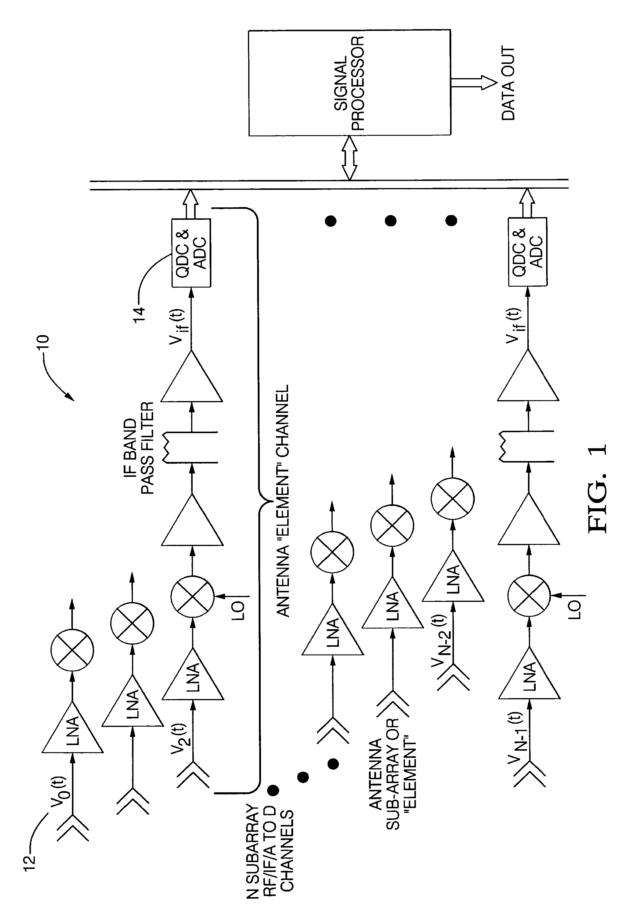
[0031]Communications systems having digital signal processing operations currently utilize an adaptive phased array antenna that acquire and track the locations of a multiplicity of broadcast stations from a mobile platform using a Digital Beam Forming (DBF) phased array antenna technique. In addition to determining the angle of arrival of a sign...


PUM


Abstract

An antenna-receiver communications system and method is provided to mechanize multibeam mobile antenna-receive subsystems. Digital beam forming for modern wideband mobile communications systems is provided. In an aspect, subsystems can simultaneously receive, acquire, track and output a multiplicity of signals from sources of different locations using a single antenna aperture from a mobile platform. The angle of arrival of a signal of interest is continuously determined. Individual phased array antenna output channels are phased aligned as required by the phased array equation and monopulse signal processing. Angle sensing and beamsteering are separated from antenna channel coherent summation. Thus, the angle sensing and beamsteering functions are not required to be computed at the data rate, but can instead be computed at a rate necessary for the beam acquisition and beam tracking function speed requirements. Signal processing computational load and system cost is reduced as compared to current systems.

Description

FIELD OF THE INVENTION[0001]The invention relates generally to communication antenna-receivers, and more particularly to digital beam forming for wideband mobile communications systems.BACKGROUND OF THE INVENTION[0002]In a stationary antenna and receiver, the antenna boresight is mechanically pointed at a communications transmitter source. As an example, in a Direct Broadcast Satellite (DBS) TV service having a receiver terminal with an 18 inch parabolic dish antenna, the antenna is pointed by mechanical means at a geostationary broadcasting satellite.[0003]In a mobile antenna-receiver, a phased array technique is commonly employed such that the phased array is used to maintain the receive antenna beam pointing at a broadcast source while the antenna-receiver platform is rotated. Since the platform typically has pitch, roll, and heading variations that change with time, rapid pointing angle changes are necessary capabilities required of the communications antenna-receiver. Thus, rel...

Claims


Application Information

Patent Timeline
Patent Type & Authority Patents(United States)
IPC IPC(8): H04B1/06
CPCH04B7/086H04B7/088H04B7/0845
Inventor REED, JOHN C.
Owner DELPHI TECH INC
Why Eureka
Try Eureka