Maximum Power Point Tracking Method and Device, and Photovoltaic Power Generation System

a maximum power point technology, applied in the field of photovoltaic technology, can solve the problems of slow system response to external condition changes, power fluctuation, and contradiction between dynamic performance and static performance of p&o, so as to improve the efficiency of tracking reduce power fluctuation near the maximum power point, and improve the dynamic performance and static performance of the photovoltaic power generation system.

Active Publication Date: 2015-12-24
BOE TECH GRP CO LTD +1
View PDF5 Cites 22 Cited by
  • Summary
  • Abstract
  • Description
  • Claims
  • Application Information

AI Technical Summary

Benefits of technology

[0040]The advantageous effects of the present invention are as follows.
[0041]The maximum power point tracking method of the invention is based on gradient variable step perturbation method, in which value of the perturbation voltage step is determined according to change of difference between two powers for two adjacent samplings, thereby reference value of output voltage of the photovoltaic array is calculated, and the reference value of the output voltage is used as reference voltage value for DC bus of inverter in a single-stage photovoltaic grid-connected inverter, or used as a given signal value for voltage close loop control of DC / DC converter in the inverter in a double-stage photovoltaic grid-connected inverter. Since speed of tracking the maximum power point is efficiently improved and power fluctuation near the maximum power point is lowered, the dynamic performance and the static performance of the photovoltaic power generation system can be efficiently improved. Furthermore, the maximum power point tracking method has simple principle, rapid tracking speed and high stability, is easy to implement, will not increase the cost for the inverter of the photovoltaic power generation system, and has general applicability.

Problems solved by technology

If a larger perturbation step is used, response of the system to external condition changes is fast, but power fluctuation near MPP is large; on the contrary, if a smaller perturbation step is used, power fluctuation near MPP is small, but response of the system to external condition changes is slow.
Therefore, there are contradictions between the dynamic performance and the static performance of P&O with fixed step.

Method used


Image

  • Maximum Power Point Tracking Method and Device, and Photovoltaic Power Generation System
  • Maximum Power Point Tracking Method and Device, and Photovoltaic Power Generation System
  • Maximum Power Point Tracking Method and Device, and Photovoltaic Power Generation System

Examples


first embodiment

[0049]In this embodiment, a maximum power point tracking method and device are provided and applied to a single-stage photovoltaic grid-connected generation system. The maximum power point tracking method of this embodiment is based on gradient variable step P&O.

[0050]A maximum power point tracking method for enabling a photovoltaic array to operate at maximum power point comprises:

[0051]step a: sampling present voltage and present current of the photovoltaic array;

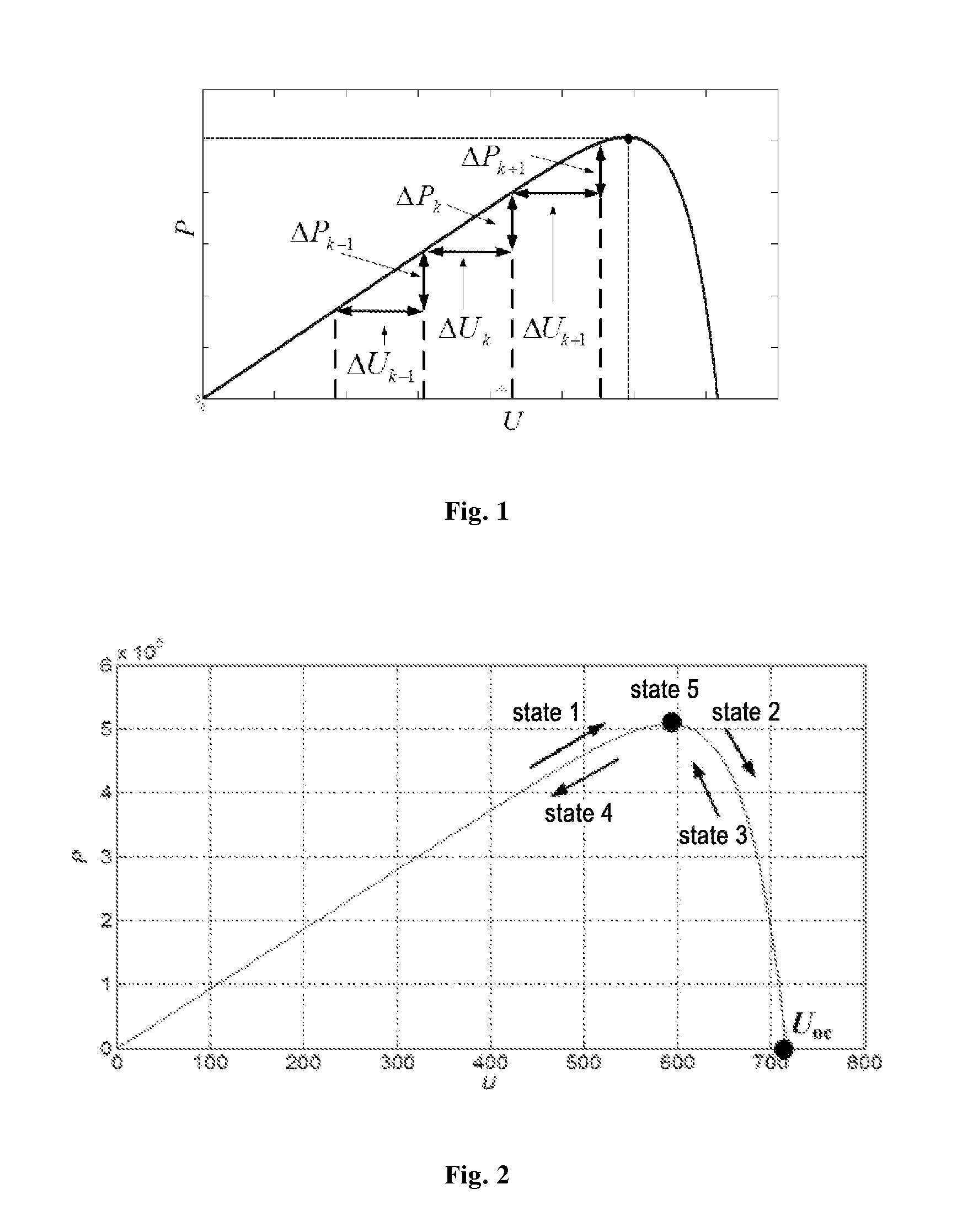
[0052]step b: obtaining present power based on the present voltage and the present current sampled at present sampling time;

[0053]step c: using a difference between the present power and power for previous sampling time as present perturbation power, and obtaining present gradient perturbation voltage step ratio based on ratio of the present perturbation power to perturbation power for previous sampling time, wherein the power for previous sampling time is obtained based on voltage for previous sampling time and current f...

second embodiment

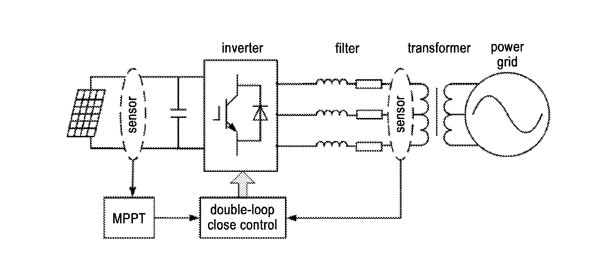
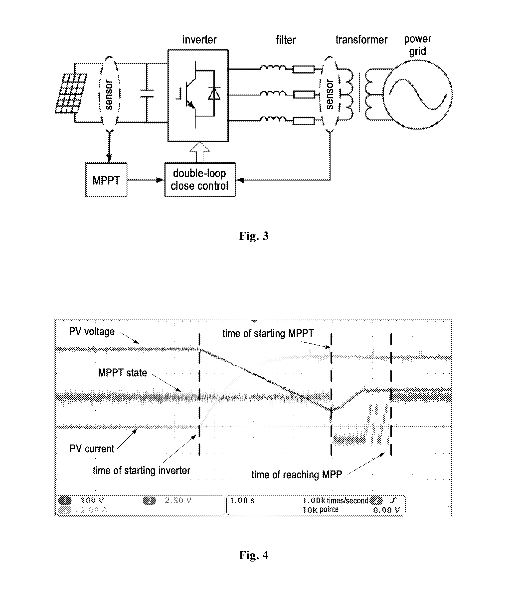
[0100]The present embodiment provides a photovoltaic power generation system. Compared with the first embodiment, the photovoltaic power generation system in the present embodiment is a double-stage photovoltaic grid-connected generation system.

[0101]The maximum power point tracking method and device in the first embodiment can be used to not only control a single-stage photovoltaic grid-connected generation system, but also control a double-stage photovoltaic grid-connected generation system. The only difference of the photovoltaic power generation system in the present embodiment from that in the first embodiment is that, the control object of the maximum power point tracking method used in the system is different. In the single-stage photovoltaic grid-connected generation system, the maximum power point tracking method is achieved by changing the voltage close-loop reference value of the DC bus, while in the double-stage photovoltaic grid-connected generation system, the maximum ...


PUM


Abstract

The present invention provides a maximum power point tracking method and device and a photovoltaic power generation system. The maximum power point tracking method comprises: sampling present voltage and present current of a photovoltaic array; obtaining present power based on the present voltage and the present current; using difference between the present power and power for previous sampling time as present perturbation power, and based on ratio of the present perturbation power to perturbation power for previous sampling time, obtaining gradient perturbation voltage step ratio; obtaining perturbation voltage step based on the gradient perturbation voltage step ratio and voltage difference between the present voltage and the voltage for previous sampling time; and controlling output voltage based on the perturbation voltage step.

Description

CROSS-REFERENCE TO RELATED APPLICATION[0001]The present application claims priority based on Chinese Patent Application No. 201410283241.1 filed on Jun. 20, 2014, the entire content of which is incorporated herein by reference.FIELD OF THE INVENTION[0002]The present invention relates to the field of photovoltaic technology, and particularly to a maximum power point tracking method and device, and a photovoltaic power generation system.BACKGROUND OF THE INVENTION[0003]Utilizing clear solar energy to generate electricity is one of the most effective means for solving the problem of current energy shortage. However, since output voltage and output current of photovoltaic array are influenced by external environment (e.g., illumination intensity, temperature, load characteristic) and factors of itself, output characteristics of photovoltaic array demonstrate obvious non-linear characteristics, with which output power thereof varies constantly. At certain illumination intensity and certa...

Claims


Application Information

Patent Timeline
Patent Type & Authority Applications(United States)
IPC IPC(8): G05F1/67G05F1/46
CPCG05F1/46G05F1/67Y02E10/56
Inventor LI, JINHAN, XIAOYANZHENG, PINGHE, JIA
Owner BOE TECH GRP CO LTD
Why Eureka
Try Eureka