
Method and apparatus for controlling variable valve system

A variable, valve timing technology, applied in the direction of valve device, electrical control, engine control, etc., can solve the problems of deterioration of combustion state of internal combustion engine, increase of exhaust emission, unsuitable characteristics of engine valve and valve, etc.

Inactive Publication Date: 2013-01-30
TOYOTA JIDOSHA KK
View PDF6 Cites 6 Cited by
  • Summary
  • Abstract
  • Description
  • Claims
  • Application Information

AI Technical Summary

Problems solved by technology

When inaccurate information is used to drive control actuators, the valve characteristics of the engine valves become unsuitable for engine operation
As a result, the combustion state of the internal combustion engine may deteriorate, resulting in a decrease in the running performance of the engine and an increase in exhaust emissions

Method used


Image

  • Method and apparatus for controlling variable valve system
  • Method and apparatus for controlling variable valve system
  • Method and apparatus for controlling variable valve system

Examples


no. 1 example

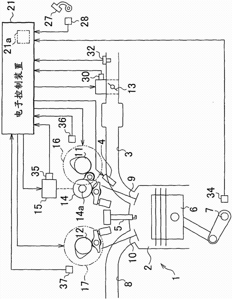
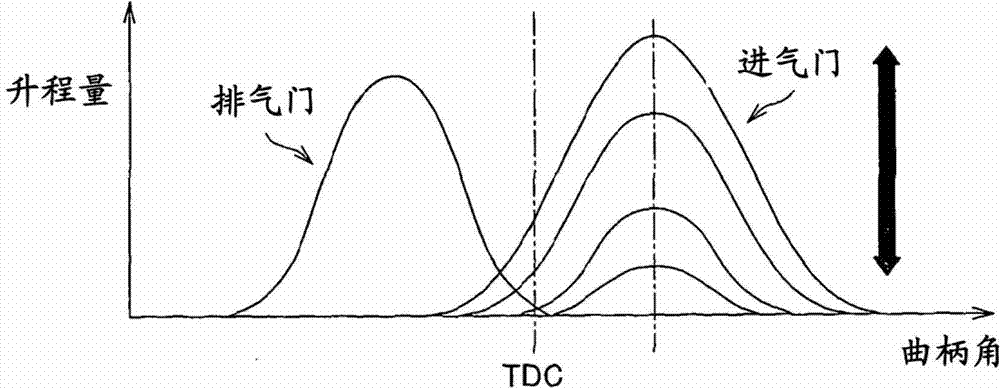
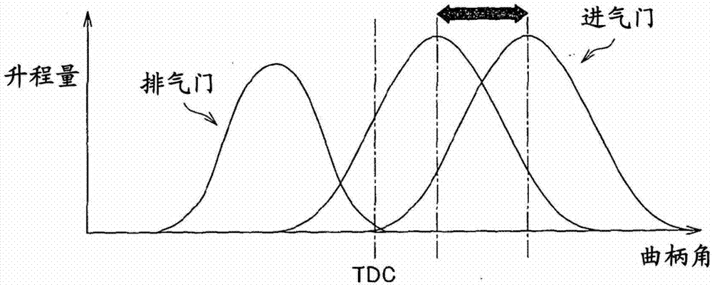
[0038] The following will refer to Figures 1 to 6 A first specific embodiment of a variable valve timing device for changing the valve characteristics of an engine valve such as an intake valve and an exhaust valve provided in an automobile engine according to the present invention will be described.

[0039] exist figure 1 In the engine 1 shown, a throttle valve 13 is arranged to be able to open and close in an intake passage 3 connected to a combustion chamber 2 of the engine 1 . Air is drawn into the cylinders via intake passage 3 , and fuel injected from fuel injection valve 4 is supplied to the cylinders via intake passage 3 . When the spark plug 5 ignites an air-fuel mixture formed of air and fuel, the air-fuel mixture burns, causing the piston 6 to reciprocate, and as a result, the crankshaft 7 serving as an output shaft of the engine 1 rotates. After being burned in the cylinder, the air-fuel mixture is discharged from the cylinder to the exhaust passage 8 as exhaus...

no. 2 example

[0085] Next, based on Figure 7 and 8 A second embodiment of the present invention will be described. In this embodiment, initialization processing with full stroke driving is always performed regardless of the presence or absence of an abnormality history, and the driving speed of the actuator 15 during the initialization processing is changed in accordance with the presence or absence of an abnormality history.

[0086] Figure 7 is a flowchart showing an initialization processing routine according to this embodiment. S301 to S304 of this initialization processing routine are equivalent to the initialization processing according to the first embodiment ( Figure 5 ) of S101 to S104. Therefore, when the abnormality history is stored in the RAM 21a of the electronic control device 21 (S301: YES), if it is judged in S302 that the execution condition is satisfied, the usual initialization processing (corresponding to the first initialization processing of the first embodimen...


PUM


Abstract

A variable valve timing apparatus for an internal combustion engine, including: an actuator (15) that activates a variable valve timing mechanism; a detection unit (35) that detects a driving position of the actuator; a control unit (21) that drive-controls the actuator, and when a predetermined execution condition is established, executes one of a first initialization process and a second initialization process that match the driving position of the actuator detected by the detection unit with an actual driving position of the actuator; and an abnormality determination unit (21) that determines whether or not an abnormality is present in the driving position detected by the detection unit and stores an abnormality history after determining that an abnormality is present. The control unit executes the first initialization process when the abnormality history is stored and the second initialization process when the abnormality history is not stored.

Description

technical field [0001] The invention relates to a variable valve timing device for an internal combustion engine and a control method thereof. Background technique [0002] A conventional variable valve timing device for an internal combustion engine includes a variable valve timing mechanism that changes valve characteristics of engine valves such as intake valves and exhaust valves, is driven within a predetermined driving range so as to actuate variable An actuator for a valve timing mechanism, and an electronic control unit for driving and controlling the actuator. [0003] In order to control the valve characteristics of the engine valves with high precision in such a variable valve timing device, it is important to accurately detect the actual valve characteristics and actuate the variable valve timing mechanism, or in other words drive the control actuator so that the actual The valve characteristics coincide with the target characteristics. Regarding the method of ...

Claims


Application Information

Patent Timeline
Patent Type & Authority Applications(China)
IPC IPC(8): F02D41/00F02D41/14
CPCF01L1/34F02D41/0002F02D41/221F02D2041/001Y02T10/42F02D41/2461Y02T10/40
Inventor 正源寺良行泷本文人中川崇羽原俊辅
Owner TOYOTA JIDOSHA KK
Learn More