Blister machine table automatic backing plate

A technology of workbench and blister machine, which is applied in the field of automatic padding of blister machine workbench, which can solve the problems of burden, large amount of maintenance, scrapping of board parts, etc., achieve less support unit parts, save manufacturing cost, and reduce motion load Effect

Active Publication Date: 2014-10-08
GUANGZHOU YUANFANG COMP SOFTWARE ENG
View PDF3 Cites 0 Cited by
  • Summary
  • Abstract
  • Description
  • Claims
  • Application Information

AI Technical Summary

Problems solved by technology

[0004] But the above-mentioned technical scheme also has the following deficiencies: 1. Due to the requirements of the plastic-absorbing process, the working backing plate needs to have a certain indentation relative to the edge of the plate to be processed. The plate to be processed needs to be placed in a suitable position so that all the pressing rods in the middle of the support body within the outline of the plate to be processed can be pressed down by the plate to be processed to achieve locking. If the support body inside is not locked
Rectangular plates can generally find a suitable position, but for L-shaped, arc-shaped and other special-shaped plates, rectangular or special-shaped plates with hollow parts, it is usually difficult to find a suitable position. At this time, this automatic backing plate cannot 2. The plate to be processed usually has a certain warpage, and its bottom surface is not a pure plane, and the locking stroke of this automatic backing plate is very small. For the part whose warping exceeds the locking stroke, the support body will fall. If the working backing plate cannot form a complete support, the board may be broken or the surface may be bent during the blister process. For high-gloss plastic film, even if the surface is bent to a small extent, the board will be scrapped. Therefore, this The automatic backing plate with passive locking is not very practical; 3. This kind of backing plate uses the point contact of steel balls and the hollow rod of the backing plate to withstand the huge pressure in the blister process, and the local pressure is very high, so high-strength materials need to be used to Manufacture, high cost, heavy weight, burdens the movement mechanism of the table top of the blister machine; 4. The control unit of the backing plate needs to enter the high-temperature and high-pressure blister furnace in the blister process, which is stable and reliable for the control system of the entire blister machine Negative impact; 5. The single backing plate is composed of 6 parts. For the work surface of the standard blister machine, the entire backing plate needs 3,486 single backing plates, with a total of 20,916 parts. The manufacturing and assembly are complicated and the maintenance is large.

Method used


Image

  • Blister machine table automatic backing plate
  • Blister machine table automatic backing plate
  • Blister machine table automatic backing plate

Examples


Embodiment 1

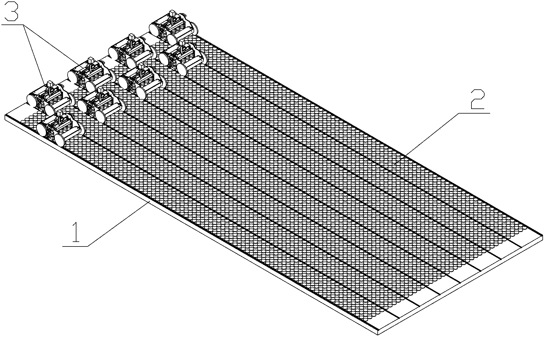
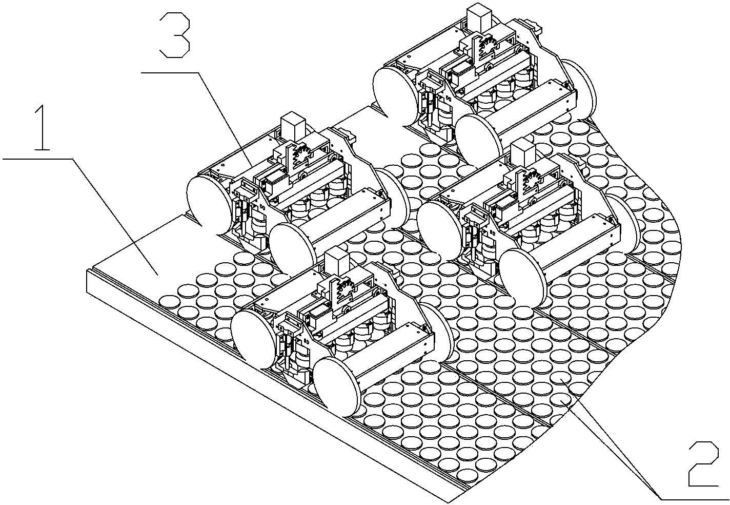
[0037] See figure 1 with figure 2 The automatic backing board of the workbench of the blister machine of this embodiment includes a backing board 1, a plurality of supporting units 2 arranged on the backing board 1, and a plurality of operating robots 3. among them,

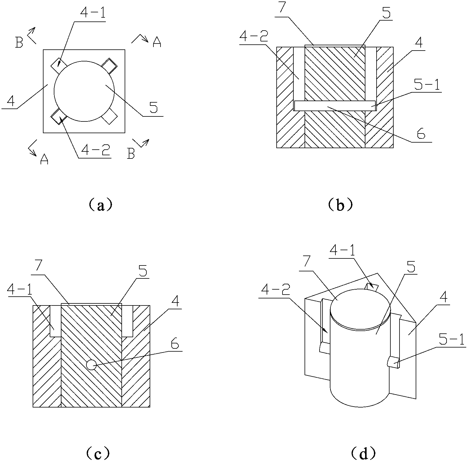
[0038] See image 3 with Figure 4 The support unit 2 includes a support base 4 and a support rod 5 that can move up and down in the support base 4. The support rod 5 is a cylinder inserted into a cylindrical hole in the support base 4. 4 and the support rod 5 are provided with a locking structure, which allows the support rod 5 to stay and support in a raised position when moving upwards to form a raised state, and to stay and support in a lowered position when moving downwards A descending state is formed; specifically, the locking structure is: two sets of sink grooves with different axial depths are provided on the wall of the cylindrical hole, wherein the smaller depth is the upper sink groove 4-1, and the lar...

Embodiment 2

[0044] See Figure 10 ~ Figure 12 The difference between this embodiment and embodiment 1 lies in the locking structure in the support unit 22. The locking structure of this embodiment is: the bottom surface of the cylindrical hole of the support base 4 is provided with a downwardly recessed rectangular groove 4- 4. The bottom surface of the circular hole forms an upper positioning step, and the bottom of the groove 4-4 forms a lower positioning step; the circumference of the bottom of the cylindrical hole extends radially outward, so that the bottom of the cylindrical hole forms a rectangular space 4 -3, and at the two opposite corners of the rectangular space 4-3 are provided with blocking portions 4-5, the inner edge of the blocking portion 4-5 extends beyond the side wall of the cylindrical hole, the role of the blocking portion 4-5 is set It limits the rotation range of the support rod 5 in the cylindrical hole; the middle of the bottom surface of the cylindrical support r...

Embodiment 3

[0048] See Figure 13 with Figure 14 In this embodiment, the locking structure is: the support rod 5 is a bolt, and the support seat 4 is provided with a nut 8 matching the bolt; the bolt realizes up and down movement when it rotates relative to the nut 8. The raised position and the lowered position are within the range of the up and down movement of the bolt, so that when the support rod 5 moves up to the raised position, it forms a raised state, and when it moves down to the lowered position, it forms a lowered state.

[0049] See Figure 14 with Figure 15 The difference between the operating machine of this embodiment and this embodiment 1 is that the operating head of this embodiment adopts the in-line transmission member 25 as the operating element that drives the support rod 5 to move, thereby replacing the operating element in embodiment 1. The lower part of the flat-shaped transmission member 25 has a flat-shaped screwdriver bit, and the upper part is a cylinder, and th...


PUM


Abstract

The invention discloses an automatic base plate for a vacuum forming machine worktable. The automatic base plate comprises a base plate, a plurality of supporting units arranged on the base plate, and at least one manipulation robot, wherein each supporting unit comprises a supporting seat and a supporting rod which is arranged in the supporting seat and can move up and down; the supporting rod can be stopped and supported at a lifting position when the supporting rod moves upwards so as to form a lifting state, and when the supporting rod moves downwards, the supporting rod can be stopped and supported at a descending position so as to form a descending state; the manipulation robot is a movable trolley and comprises a frame, a traveling device, and a lifting device, a positioning device and a controller which are arranged on the frame; the lifting device comprises a lifting frame and a lifting motor; an operation head is arranged on the lifting frame; and the operation head acts on the supporting rod and lift up or put down the supporting rod to an ascending position or a descending position along with the lifting frame. According to the automatic base plate, the state of the supporting units can be actively changed, and the automatic base plate has the advantages of simple structure, light weight and the like.

Description

Technical field [0001] The invention relates to a workbench component of a blister machine, in particular to an automatic pad of the workbench of a blister machine. Background technique [0002] At present, the automatic backing plate of the workbench of the domestic blister machine mainly adopts an imported computer-controlled automatic backing system. A large number of small backing plates with small electromagnetic devices at the bottom are combined into a large backing plate. The computer control system controls each plate during operation. The raising and lowering of each position is controlled one-to-one, and the raised small pad is locally combined to form a working pad that is a certain distance above the worktable, and then the plastic suction process is carried out. Because the control unit of this automatic pad is integrated with the small pad, thousands of control units need to enter the high temperature and high pressure blister furnace in the blister process. The la...

Claims


Application Information

Patent Timeline
Patent Type & Authority Patents(China)
IPC IPC(8): B29C51/26
Inventor 彭劲雄
Owner GUANGZHOU YUANFANG COMP SOFTWARE ENG
Why Eureka
Try Eureka