
Robot for brushing ship body

A robot and cleaning technology, which is applied to the cleaning equipment of ship liquid tanks, oil tank ships, motor vehicles, etc., can solve the problems of affecting the compass, the distance becomes larger, and the steering is difficult, so as to overcome the negative impact, improve the safety performance, prevent unintended effects

Active Publication Date: 2013-02-06
海南斑斓海洋科技有限公司
View PDF6 Cites 12 Cited by
  • Summary
  • Abstract
  • Description
  • Claims
  • Application Information

AI Technical Summary

Problems solved by technology

[0002] Most of the current hull cleaning robots use magnetic adsorption robots. As we all know, if the side of the ship is not cleaned for many years, a thick layer of shellfish will grow. When the magnetic adsorption robot When walking here, the distance between the hull and the magnetic adsorption track will become larger, which will lead to partial or even complete failure of the magnetic adsorption method. At this time, if you simply increase the magnetic force of the permanent magnet or extend the length of the track to increase the adsorption force, it will It is more difficult and more energy-intensive for the cleaning robot to turn when cleaning the surface of the hull, and the long-term use of magnetic adsorption cleaning brushes will cause the hull to become magnetic. Usually, when the communication facilities on the ship cannot work normally due to power shortages or abnormal equipment , People tend to use the compass to identify the direction, but if the hull is magnetized by the magnetic adsorption cleaning robot, it will affect the direction of the guide, so it can be seen that the damage of the magnetized hull is great

Method used


Image

  • Robot for brushing ship body
  • Robot for brushing ship body

Examples


Embodiment Construction

[0023] A hull cleaning robot of the present invention will be described in further detail below through specific embodiments.

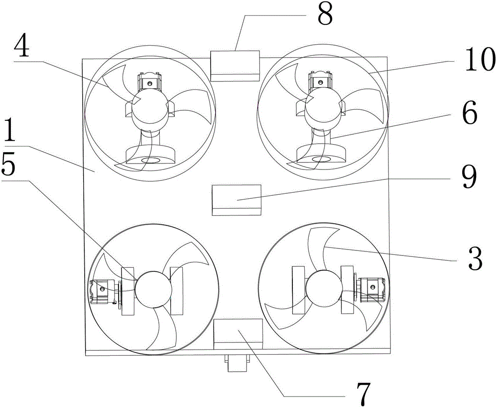
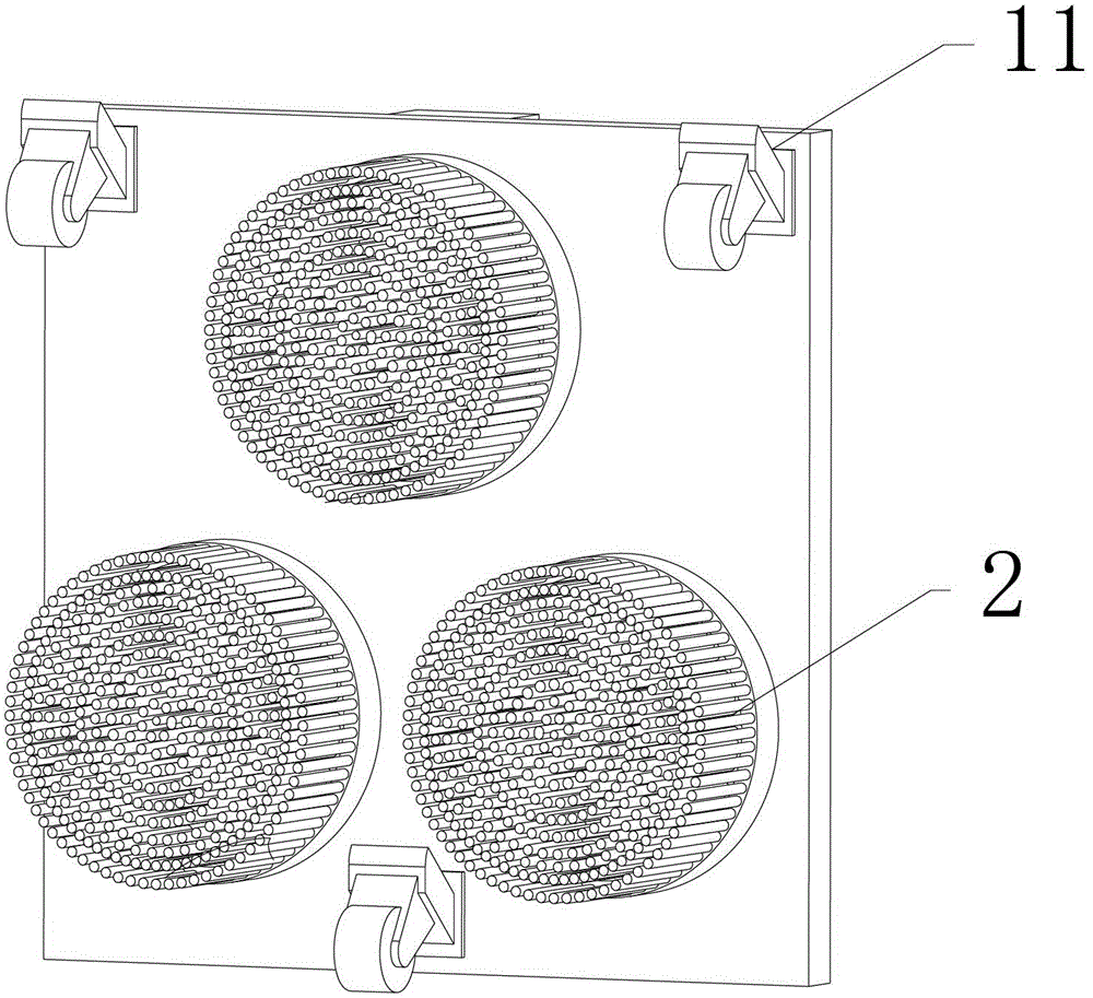
[0024] In this embodiment, the side of the hull cleaning robot that enters the water the most is the bottom, and the side that enters the water last is the top. figure 1 and 2 The up and down shown are consistent. The extension direction of the X rotation axis in the present invention is arbitrarily selected, and the extension direction of the Y rotation axis is perpendicular to the direction of the X axis.

[0025] Such as figure 1 , shown in 2, a hull cleaning robot includes a mounting plate 1, and the robot also includes a traveling wheel mechanism, a cleaning brush 2 and a rotor, the rotor is driven by a rotor rotating power device, and the rotor rotating power device is a hydraulic motor or an electric motor , the walking wheel mechanism and the cleaning brush 2 are installed on the front of the mounting plate 1, and a rotating mechanism is in...


PUM


Abstract

The invention discloses a robot for brushing a ship body. The robot comprises a mounting plate; and the robot further comprises a travelling wheel mechanism, a cleaning brush and a rotary wing, wherein the rotary wing is driven by a rotating power device of the rotary wing, the travelling wheel mechanism and the cleaning brush are installed on the front side of the mounting plate, a rotary mechanism is installed on the back side of the mounting plate and comprises a rotating shaft and a rotating shaft power device, the rotating shaft is driven by the power device of the power device, the rotary wing is fixedly connected with the rotating shaft and swings along with the rotation of the rotating shaft. The rotating power device of the rotary wing drives the rotary wing to rotate, so that the robot for brushing the ship body can be adhered to the surface of the ship body, the adhesion force is strong, and the robot not only is applicable to the ship bodies with thick shellfish attachment, but also effectively overcomes the adverse impacts of magnetic adsorption on the ship bodies; and the rotary wing swings along with the rotation of the rotating shaft, so that the travelling direction of the robot for brushing the ship body is controlled through adjusting the rotation direction of the rotary wing which rotates along with the rotating shaft.

Description

technical field [0001] The invention relates to the field of hull cleaning robots, in particular to a rotor-propelled hull cleaning robot. Background technique [0002] Most of the current hull cleaning robots use magnetic adsorption robots. As we all know, if the side of the ship is not cleaned for many years, a thick layer of shellfish will grow. When the magnetic adsorption robot When walking here, the distance between the hull and the magnetic adsorption track will become larger, which will lead to partial or even complete failure of the magnetic adsorption method. At this time, if you simply increase the magnetic force of the permanent magnet or extend the length of the track to increase the adsorption force, it will It is more difficult and more energy-intensive for the cleaning robot to turn when cleaning the surface of the hull, and the long-term use of magnetic adsorption cleaning brushes will cause the hull to become magnetic. Usually, when the communication facili...

Claims


Application Information

Patent Timeline
IPC IPC(8): B63B57/00
Inventor 陈东良国云飞刘桂芳王臣业陈东华刘富强
Owner 海南斑斓海洋科技有限公司
Learn More