Steel tube concrete column high-altitude construction safety protection system

A steel pipe concrete column and high-altitude construction technology, which is applied in the direction of building structure support, building structure support, building structure support scaffolding, etc., can solve the problems of potential safety hazards, scaffold disintegration and collapse, and complicated installation, so as to save materials, assemble and disassemble Simple and fast, easy and fast disassembly and assembly

Active Publication Date: 2013-02-06
GUANGZHOU JISHI CONSTR GRP +1
View PDF11 Cites 8 Cited by
  • Summary
  • Abstract
  • Description
  • Claims
  • Application Information

AI Technical Summary

Problems solved by technology

The existing method is mainly to build a complete scaffolding frame, and laying scaffolding boards on the scaffolding as a working platform and walking aisle. With this method, the installation is complicated and the disassembly is slow. Every time a layer of construction is completed, another layer of scaffolding needs to be built The construction of the upper layer of the building often delays the construction period, and an overall scaffolding structure is like another building, requiring a large amount of scaffolding materials
In addition, when constructing high-rise buildings, it is difficult for the scaffolding to form a firm and stable structure at high altitudes. If a connection point becomes loose and falls off, the scaffolding may disintegrate and collapse, posing a safety hazard. Therefore, the existing scaffolding system is not suitable for high-altitude steel pipe columns. Construction of pouring concrete

Method used


Image

  • Steel tube concrete column high-altitude construction safety protection system
  • Steel tube concrete column high-altitude construction safety protection system
  • Steel tube concrete column high-altitude construction safety protection system

Examples


Embodiment Construction

[0023] The specific embodiments of the present invention will be described in detail below with reference to the accompanying drawings.

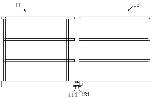
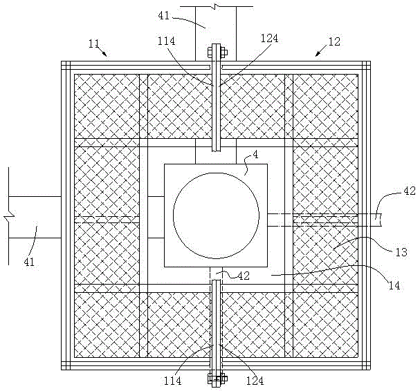
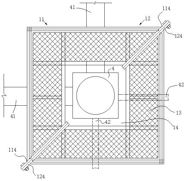
[0024] The technical scheme of the present invention is especially suitable for the construction of steel tube concrete columns in high-rise buildings. Each steel tube column is generally 2 to 3 stories high. The steel tube column is a hollow steel tube with grouting holes on the top surface. The steel tube concrete column referred to in the present invention refers to It is a combination of steel tube column and concrete after pouring concrete. During construction, after each section of steel pipe column is hoisted in place, the concrete inside the column is poured. After pouring a layer of steel pipe column, a layer of steel pipe column is hoisted and welded on the top of the layer of steel pipe column, and the upper layer of steel pipe The columns are constructed before the lower floor. Therefore, every time the concrete pouring in the steel...


PUM


Abstract

The invention discloses a steel tube concrete column high-altitude construction safety protection system which comprises a safety operation platform for executing concrete casting work on a steel tube column of the current layer and executing welding work on a steel tube column of the last layer, a safety climbing ladder which is welded on the outer sides of the steel tube columns and is used for making a constructor climb up and down the operation platform, and temporary packways which are fixed on two adjacent steel tube columns and are connected to the two adjacent steel tube columns, wherein the operation platform is a cage body fixedly arranged at an opening above the top of each steel tube column; the cage body can be split off and is separated from the steel tube columns; and a detachable supporting bracket for supporting the cage body are arranged on the top of each layer of steel tube column. By utilizing the technical scheme, the operation platform is mounted and dismounted quickly and easily and can be reused for casting the concrete to the steel tube columns; materials are saved; the operation platform, the safety climbing ladder and the temporary packways form a complete high-altitude construction three-dimensional protection system; the efficiency of steel tube concrete column construction is improved; and the working period is saved.

Description

Technical field [0001] The invention relates to the field of building construction, in particular to a safety protection system for steel pipe column concrete pouring high-altitude construction. Background technique [0002] Concrete-filled steel tube refers to a structural member formed by filling concrete in a steel tube, and the steel tube and its core concrete can bear the external load together. According to different cross-sectional forms, it can be divided into concrete filled steel tube, square and rectangular steel tube concrete and polygonal steel tube concrete, etc. . The basic principle is: Fill steel pipe with concrete. Under the action of force, the concrete has a strong effect on the steel pipe, but at the same time the steel pipe restrains the concrete, so that the concrete in the pipe is in a three-way compression stress state, delaying the occurrence of longitudinal micro-cracks. And development, thereby improving its compressive strength and compressive deform...

Claims


Application Information

Patent Timeline
Patent Type & Authority Applications(China)
IPC IPC(8): E04G21/32E04G3/24E04G5/10
Inventor 丁昌银何炳泉周岳陈慕贞汤文波刘晗晨仕召平柯德辉雷雄武
Owner GUANGZHOU JISHI CONSTR GRP
Why Eureka
Try Eureka