Pressure fittings for pressurized coring tools

A technology of pressure-bearing devices and tools, which is applied in the field of pressure-bearing devices, can solve problems such as damage to the performance of the outer cylinder, and achieve the effects of automatic pressure relief, convenient production, and improved work efficiency and reliability

Active Publication Date: 2016-01-20
CCDC PETROLEUM CORING TECH
View PDF7 Cites 0 Cited by
  • Summary
  • Abstract
  • Description
  • Claims
  • Application Information

AI Technical Summary

Problems solved by technology

[0004] The purpose of the present invention is to overcome the above-mentioned problems existing in the existing pressurized coring technology, and to provide a pressure-bearing device suitable for pressurized coring tools. The problem of wearing pins to damage the performance of the outer cylinder can achieve the purpose of not damaging the structure and performance of the outer cylinder

Method used


Image

  • Pressure fittings for pressurized coring tools
  • Pressure fittings for pressurized coring tools
  • Pressure fittings for pressurized coring tools

Examples


Embodiment 1

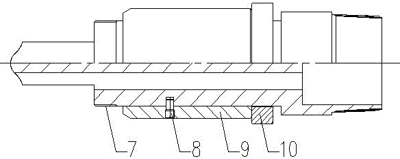
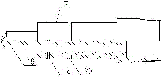
[0035] A pressure-bearing device suitable for pressurized coring tools, including a pressure-bearing assembly and a pin component, the pressure-bearing assembly includes a pressure-bearing piston 7 and a pressure-bearing sleeve 9 sleeved on the pressure-bearing piston 7, The pin part includes a shear pin 8, the upper end of the pressure-bearing piston 7 is limited in the pressure joint 5 in the hexagonal sleeve 3 by the pressure-bearing steel ball 6, and the pressure-bearing steel ball 6 can transmit the pressure to the pressure-bearing piston 7, The lower end is the connection end connected with the rotating assembly 12, the pressure bearing sleeve 9 is fixedly connected with the pressure bearing piston 7 through the shear pin 8, the lower end of the pressure bearing sleeve 9 is limited on the outer cylinder short 11, and the upper end of the pressure bearing piston 7 is provided with A sand release hole 18 and a flow channel 19 communicated with the inner cavity of the pressu...

Embodiment 2

[0046] In this embodiment, when the present invention is applied to a pressurized coring tool, it will be described in detail in conjunction with other components of the pressurized coring tool.

[0047] The pressurized coring tool involved includes an upper joint 1, a hexagonal rod 2, a hexagonal sleeve 3, an outer cylinder short 11, an outer cylinder 13, a difference short 15, an inner cylinder assembly 14, and a core bit 17. The sleeve 3 is connected to the outer cylinder 13 through the outer cylinder short 11, the outer cylinder 13 is connected to the differential short 15, and the differential short 15 is connected to the core bit 17, and also includes a pressure bearing device, a rotating assembly 12 and a core claw Assembly 16.

[0048] The specific description of the pressure-bearing device is as follows:

[0049] The pressure-bearing device includes a pressure-bearing assembly and a pin component. The pressure-bearing assembly includes a pressure-bearing piston 7 and...

Embodiment 3

[0072] In this embodiment, when the present invention is applied to a pressurized coring tool, the connection and working process of the pressurized coring tool are described in detail.

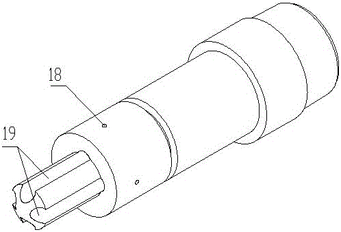
[0073] The pressure-bearing piston is arranged in the middle section of the pressurized coring tool, and a sand discharge hole 18 and a flow channel 19 are arranged at the front end of the pressure-bearing piston 7, and four flow channels 19 are arranged at the front end of the pressure-bearing piston 7, and the flow channel 19 is a groove shape, and three sand discharge holes 18 are arranged on the circumference of the pressure-bearing piston 7 at the rear end of the flow channel 19; the upper end of the pressure-bearing piston 7 is blocked by the pressure-bearing steel ball 6 in the pressure joint 5 of the coring tool , the upper end of the pressure joint 5 is a hexagonal rod 2, and a rubber seal 4 is arranged between the hexagonal rod 2 and the pressure joint 5; the hexagonal rod 2, the pre...


PUM


Abstract

The invention discloses a pressure bearing device suitable for a pressurized coring tool, which includes a pressure bearing assembly and a pin component, wherein the pressure bearing assembly includes a pressure bearing piston and a pressure bearing sleeve arranged on the pressure bearing piston in a sleeving manner; the pin component includes a shear pin; the upper end of the pressure bearing piston is limited on a pressurized connector in a hexagonal sleeve through a pressure bearing steel ball, and the lower end of the pressure bearing piston is a connecting end connected with a rotary assembly; the pressure bearing sleeve is fixedly connected with the pressure bearing piston through the shear pin; the lower end of the pressure bearing sleeve is limited on a short joint of an outer cylinder; and sand discharge holes and flow channels communicated with an inner chamber of the pressure bearing piston are arranged at the upper end of the pressure bearing piston. The pressure bearing device solves the problem that the conventional pressurized coring tool damages the performance of the outer cylinder as a pin penetrates through the outer cylinder, and achieves the purpose that the structure and performance of the outer cylinder are not damaged.

Description

technical field [0001] The invention relates to a pressure-bearing device suitable for a pressurized coring tool, which is used for oil and gas drilling operations, and belongs to the technical field of oil and gas coring equipment manufacturing. Background technique [0002] In the existing pressurized coring technology, there are two situations: 1. There is no pressure-bearing sleeve in the pressurized coring tool, and the pin is directly inserted between the outer cylinder and the pressure-bearing piston; 2. The pressurized coring tool There is a pressure bearing sleeve in the tool, and a pin passes between the pressure bearing piston and the pressure bearing sleeve. For example, Chinese Patent No. "200720005569.2" discloses a mechanically pressurized joint, which was disclosed on January 30, 2008, including a large joint, a hexagonal rod with a groove at the tail, a hexagonal sleeve, a differential rigid body, and a pressure bearing rod. , wherein the large joint is fix...

Claims


Application Information

Patent Timeline
Patent Type & Authority Patents(China)
IPC IPC(8): E21B25/00
Inventor 陈立陈晓彬刘彬胡畔何超李伟成邓元洲唐聪
Owner CCDC PETROLEUM CORING TECH
Why Eureka
Try Eureka