Pressurized coring tool

A tool and coring technology, applied in the direction of extracting undisturbed core devices, earthwork drilling and mining, etc., can solve the problems of easy broken cores

Active Publication Date: 2013-01-30
BC P INC CHINA NAT PETROLEUM CORP +1
View PDF11 Cites 8 Cited by
  • Summary
  • Abstract
  • Description
  • Claims
  • Application Information

AI Technical Summary

Problems solved by technology

[0005] The object of the present invention is to overcome the above-mentioned problems existing in existing coring tools when they are used for coring broken formations, and to provide a pressurized coring tool. In the process of coring, the inner cylinder of the pressurized tool It can rotate with the rotation of the drilling tool, which solves the problem that the rock core entering the inner barrel is easily broken

Method used


Image

  • Pressurized coring tool
  • Pressurized coring tool
  • Pressurized coring tool

Examples


Embodiment 1

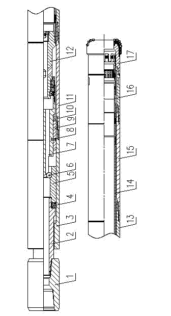
[0049] A pressurized coring tool, including an upper joint 1, a hexagonal rod 2, a hexagonal sleeve 3, an outer cylinder short 11, an outer cylinder 13, a differential short 15, an inner cylinder assembly 14, a core bit 17, and a hexagonal sleeve 3 Connect the outer cylinder 13 with the outer cylinder short 11, the outer cylinder 13 is connected with the difference short 15, and the difference short 15 is connected with the core bit 17, and also includes a pressure bearing device, a rotating assembly 12 and a core claw combination piece 16.

[0050] The specific description of the pressure-bearing device among the present invention is as follows:

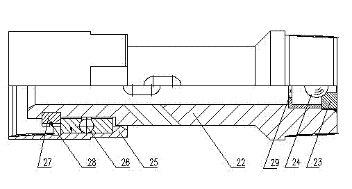
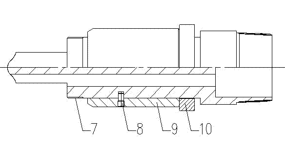
[0051] The pressure-bearing device includes a pressure-bearing assembly and a pin component. The pressure-bearing assembly includes a pressure-bearing piston 7 and a pressure-bearing sleeve 9 sleeved on the pressure-bearing piston 7. The pin component includes a shear pin 8. The pressure-bearing piston 7 The upper end is limited by...

Embodiment 2

[0072] The present invention is described in further detail below:

[0073]The pressure-bearing piston is arranged in the middle section of the pressurized coring tool, and a sand discharge hole 18 and a flow channel 19 are arranged at the front end of the pressure-bearing piston 7, and four flow channels 19 are arranged at the front end of the pressure-bearing piston 7, and the flow channel 19 is a groove shape, and three sand discharge holes 18 are arranged on the circumference of the pressure-bearing piston 7 at the rear end of the flow channel 19; the upper end of the pressure-bearing piston 7 is blocked by the pressure-bearing steel ball 6 in the pressure joint 5 of the coring tool , the upper end of the pressure joint 5 is a hexagonal rod 2, and a rubber seal 4 is arranged between the hexagonal rod 2 and the pressure joint 5; the hexagonal rod 2, the pressure joint 5 and the seal rubber 4 are arranged in the hexagonal sleeve 3 The upper end of the hexagonal rod 2 is conn...


PUM


Abstract

The invention discloses a pressurized coring tool comprising a pressure bearing device, a rotating assembly and a core catcher assembly, wherein the pressure bearing device comprises a pressure bearing assembly and a pin component, the pressure bearing assembly comprises a pressure bearing piston and a pressure bearing sleeve sheathed on the pressure bearing piston, the pin component comprises a shearing pin; the rotating assembly comprises a core shaft, one end of the core shaft is provided with a rotating device, the other end of the core shaft is provided with an automatic pressure relieving assembly; and the core catcher assembly comprises a connecting sleeve, a clamp seat, a clamp, a pressurized core catcher and a self-locking core catcher, one end of the clamp seat is connected with the lower end of the connecting sleeve, the other end of the clamp seat is connected with the pressurized core catcher, the upper end of the connecting sleeve is connected with an internal cylinder assembly, the clamp is arranged in the clamp seat, and the self-locking core catcher is arranged in the pressurized core catcher. When the pressurized coring tool disclosed by the invention is used for coring, the internal cylinder of a pressurizing tool can rotate along with the rotation of a drilling tool, and the problem that a core entering into the internal cylinder breaks easily is solved.

Description

technical field [0001] The invention relates to a pressurized coring tool, which is used for coring oil and gas wells, and belongs to the technical field of design and manufacture of drilling coring tools. Background technique [0002] In the process of oil and gas drilling, in order to understand the oil and gas content of the downhole formation, usually according to the designed well depth, it is necessary to drill the cores of different layers underground. In order to obtain better cores, when drilling The heart requires the use of specialized coring tools. [0003] According to different formations, coring tools currently mainly include conventional coring tools and special coring tools, among which conventional coring tools include self-locking coring tools and pressurized coring tools; the patent number is CN200620149089.9 A new type of mechanically pressurized coring tool is disclosed, which discloses a mechanically pressurized coring tool, which mainly solves the pr...

Claims


Application Information

Patent Timeline
Patent Type & Authority Applications(China)
IPC IPC(8): E21B25/00E21B25/10
Inventor 胡畔刘彬何超邓元洲陈立唐聪李伟成陈文才卢记坡
Owner BC P INC CHINA NAT PETROLEUM CORP
Why Eureka
Try Eureka