Bearing cage segment, bearing cage and method for manufacturing the same

A bearing cage and cage technology, applied in the direction of bearings, bearing components, roller bearings, etc., can solve the problems such as the inability to guarantee the guiding function of the plastic cage, the strength limit, the high manufacturing cost, etc., and achieve good emergency operation characteristics, outstanding Friction characteristics, effect of low running noise

Active Publication Date: 2013-02-06
AB SKF
View PDF6 Cites 7 Cited by
  • Summary
  • Abstract
  • Description
  • Claims
  • Application Information

AI Technical Summary

Problems solved by technology

Due to this high coefficient of thermal expansion, the guiding effect of the plastic cage cannot be guaranteed
In addition, due to this higher coefficient of thermal expansion, there is also reduced dimensional stability in relation to the diameter of the bearing cag

Method used


Image

  • Bearing cage segment, bearing cage and method for manufacturing the same
  • Bearing cage segment, bearing cage and method for manufacturing the same
  • Bearing cage segment, bearing cage and method for manufacturing the same

Examples


Example Embodiment

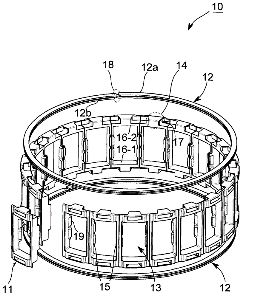
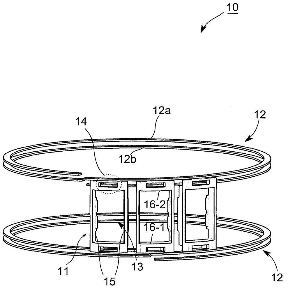
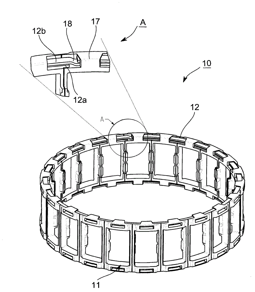
[0033] figure 1 Shown is a perspective view of a bearing cage 10 with a plurality of separate cage pieces 11 (which can be mounted on two axially spaced apart lamellar support rings 12 ), an uncompleted bearing cage 10 , and a diagram for example only.

[0034] A plurality of bearing cage segments 11 are used to support rolling bodies (not shown) in rolling body pockets 13 formed by the bearing cage segments 11 . For this purpose, the bearing cage section 11 comprises at least two circumferential connection sections 16 - 1 , 16 - 2 arranged in the circumferential direction and axially spaced at a certain distance. Furthermore, at least one connecting web 15 connecting the circumferential connecting sections 16 - 1 , 16 - 2 is arranged in a bearing cage section 11 , so that two The bearing cage section 11 forms at least one pocket 13 or window for bearing rolling elements. Although it is sufficient for this to arrange exactly one connecting web 15 per bearing cage section 11 ...


PUM


Abstract

The embodiment of the invention relates to a bearing cage used for rolling bearings. The bearing cage (10) has a plurality of bearing cage segments (11) for accommodating rolling bodies in rolling body pockets (13) formed through the bearing cage segments (11). Each bearing cage segment comprises a coupling arrangement (14), which is formed to arrange the segments on a carrier ring (12) that is formed as a lamellar ring. The bearing cage (10) has at least one carrier ring (12) that is formed as a lamellar ring, the carrier ring (12) brings the segments on the carrier ring by the coupling arrangement (14), so that at least one rolling body pocket (13) is formed by two bearing cage segments (11) arranged in a circumferential direction adjacent to the carrier ring.

Description

technical field [0001] The invention relates to a bearing cage segment for a rolling bearing, a bearing cage composed of such a bearing cage segment and a support ring, and a method for producing such a bearing cage. Background technique [0002] The bearing cage used for rolling bearings generally consists of two side rings arranged at a certain distance in the axial direction and a number of lintels connected to the side rings and arranged in sequence in the circumferential direction of the bearing cage. The lintels form pairs A pocket that accommodates rolling elements. The bearing cage keeps the rolling elements at a distance from each other by being equipped with pockets arranged for this purpose and prevents direct contact of adjacent rolling elements, which can effectively reduce friction and heat generation in the bearing. In addition, the cage enables the rolling elements to be equally distributed over the entire circumference of the cage or rolling bearing and ach...

Claims


Application Information

Patent Timeline
IPC IPC(8): F16C33/51
CPCF16C33/467F16C33/4611B21D53/12F16C33/502F16C33/4664F16C2300/14F16C19/24Y10T29/49691
Inventor B·贝克B·贝福斯G·瓦格纳H-J·弗里德里克A·拉迪纳J·谢尔林W·施耐德J·韦格雷恩
Owner AB SKF
Why Eureka
Try Eureka