

Orifice plate for engine mount filled with magnetorheological fluid
一种磁流变流体、发动机的技术,应用在动力装置、喷气推进装置、内燃推进装置等方向,能够解决增加热量、降低控制效率、尺寸增加等问题,达到控制性能提高的效果
- Summary
- Abstract
- Description
- Claims
- Application Information
AI Technical Summary
Problems solved by technology
Method used
Image

Examples
Embodiment Construction
[0042] Reference will now be made in detail to various embodiments of the invention, examples of which are illustrated in the accompanying drawings and described below. While the invention will be described in conjunction with exemplary embodiments, it will be appreciated that present description is not intended to limit the invention to those exemplary embodiments. On the contrary, the invention is intended to cover not only the exemplary embodiments but also various alternatives, modifications, equivalents and other alternatives, modifications, equivalents and others, which may be included within the spirit and scope of the invention as defined by the appended claims. implementation plan.
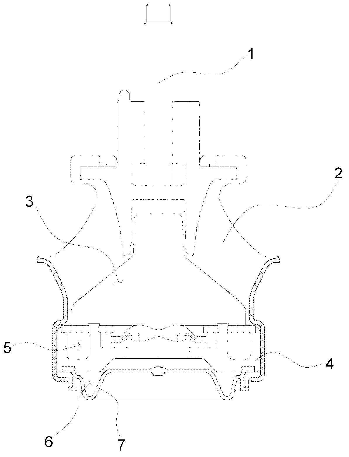
[0043] Hereinafter, an orifice plate for an engine mount filled with MR fluid according to an exemplary embodiment of the present invention will be described in detail with reference to the accompanying drawings.
[0044] An orifice plate according to an exemplary embodiment of the prese...
PUM
 Abstract
Description
Claims
Application Information