Air bleed valve float arrangement with restrictor

Inactive Publication Date: 2014-12-04
EATON CORP
View PDF8 Cites 0 Cited by
  • Summary
  • Abstract
  • Description
  • Claims
  • Application Information

AI Technical Summary

Benefits of technology

The patent describes a new bleed valve assembly for hydraulic systems. The valve prevents air from leaking into the system and allows air to escape when there is excess pressure. The valve can also continue to bleed air even when the system is under constant pressure. This solves the problem of hydraulic fluid leakage and aeration that can damage the system and reduce its lifespan.

Problems solved by technology

A typical problem that can occur in hydraulic systems is aeration.
This implosion of air releases large amounts of energy that can result in damage to the pump, which over time can result in premature failure of the pump.
While prior art air-vent valves have been used to release air in the hydraulic system, such valves do not protect against hydraulic leakage from the valve as a result of a valve component failure.
Leakage in hydraulic systems can be problematic since it drains the hydraulic system of hydraulic fluid.
As previously stated, the risk of aeration in the hydraulic system increases as the amount of hydraulic fluid in the hydraulic system decreases, which potentially decreases the life of the components of the hydraulic system.
Excess air pressure within the passageway, however, tends to lift the float ball in the valve, thus closing the air passage.
Maintaining continuous bleeding of air in such systems, then, can be difficult.

Method used


Image

  • Air bleed valve float arrangement with restrictor
  • Air bleed valve float arrangement with restrictor
  • Air bleed valve float arrangement with restrictor

Examples


Embodiment Construction

[0013]Reference will now be made in detail to the exemplary aspects of the present disclosure that are illustrated in the accompanying drawings. Wherever possible, the same reference numbers will be used throughout the drawings to refer to the same or like structure. The technologies described herein may be utilized in hydraulic systems and hydraulic system bleed valve assemblies, such as those described in U.S. Pat. No. 8,333,217, the disclosure of which is hereby incorporated by reference herein in its entirety.

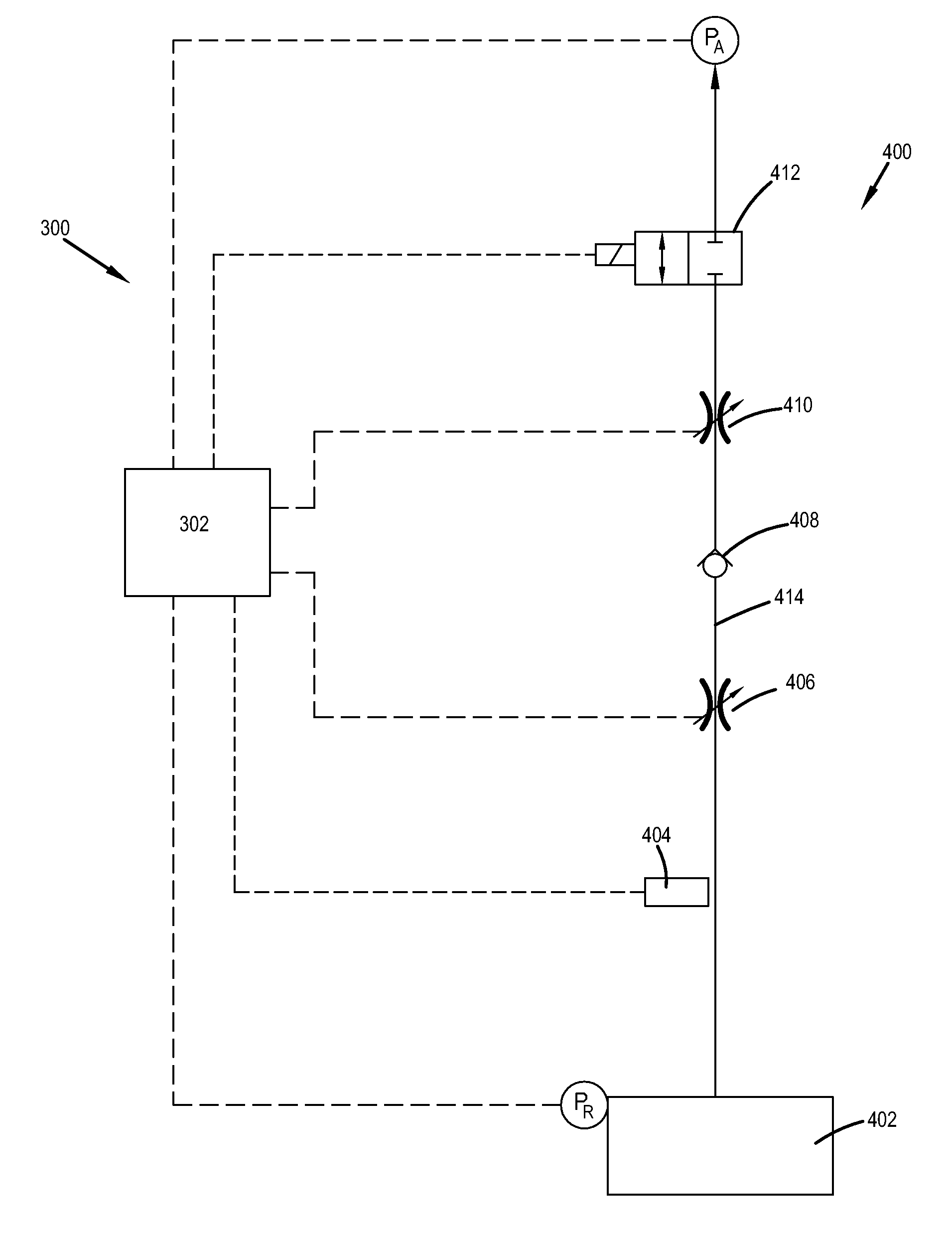
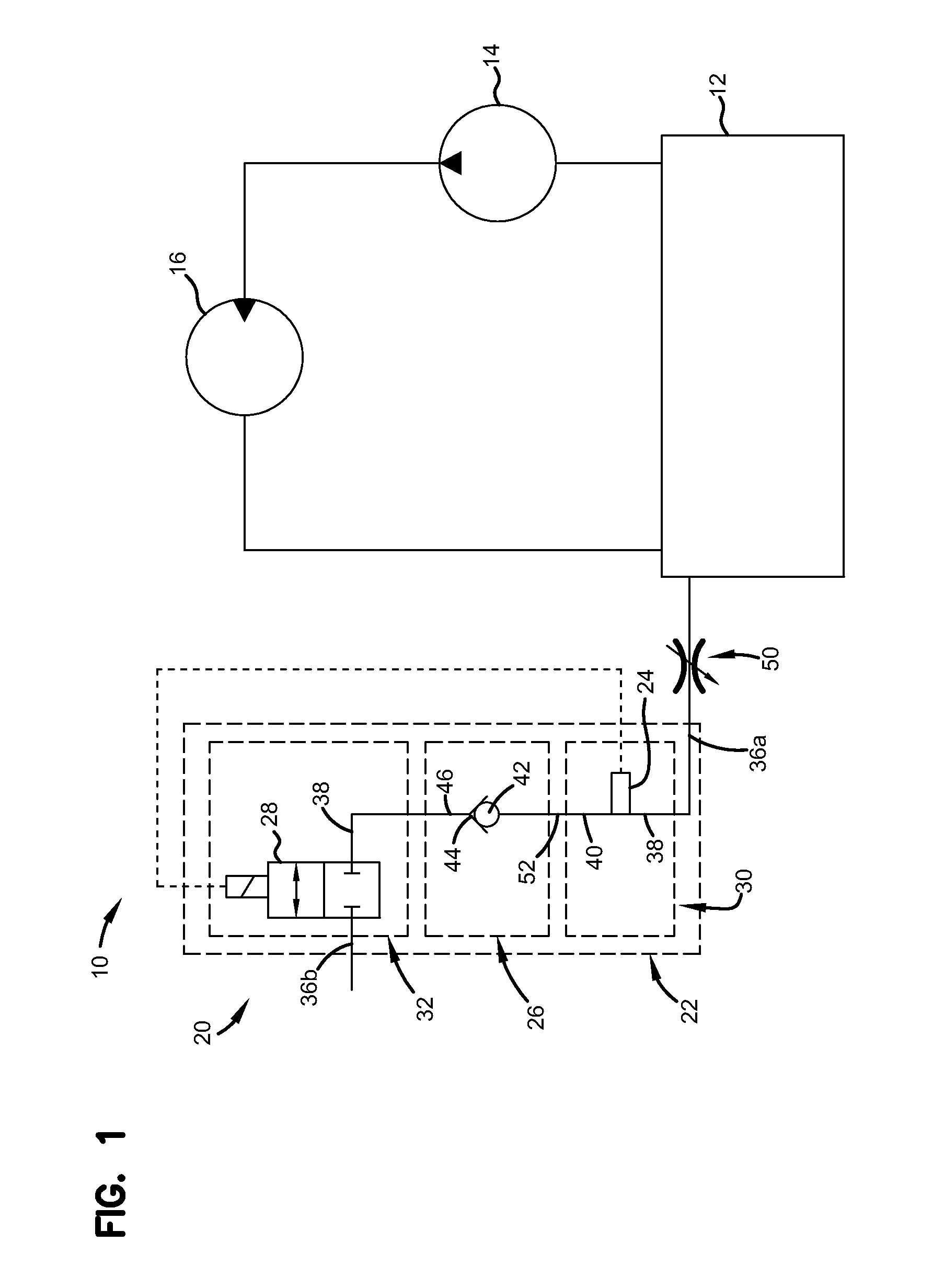
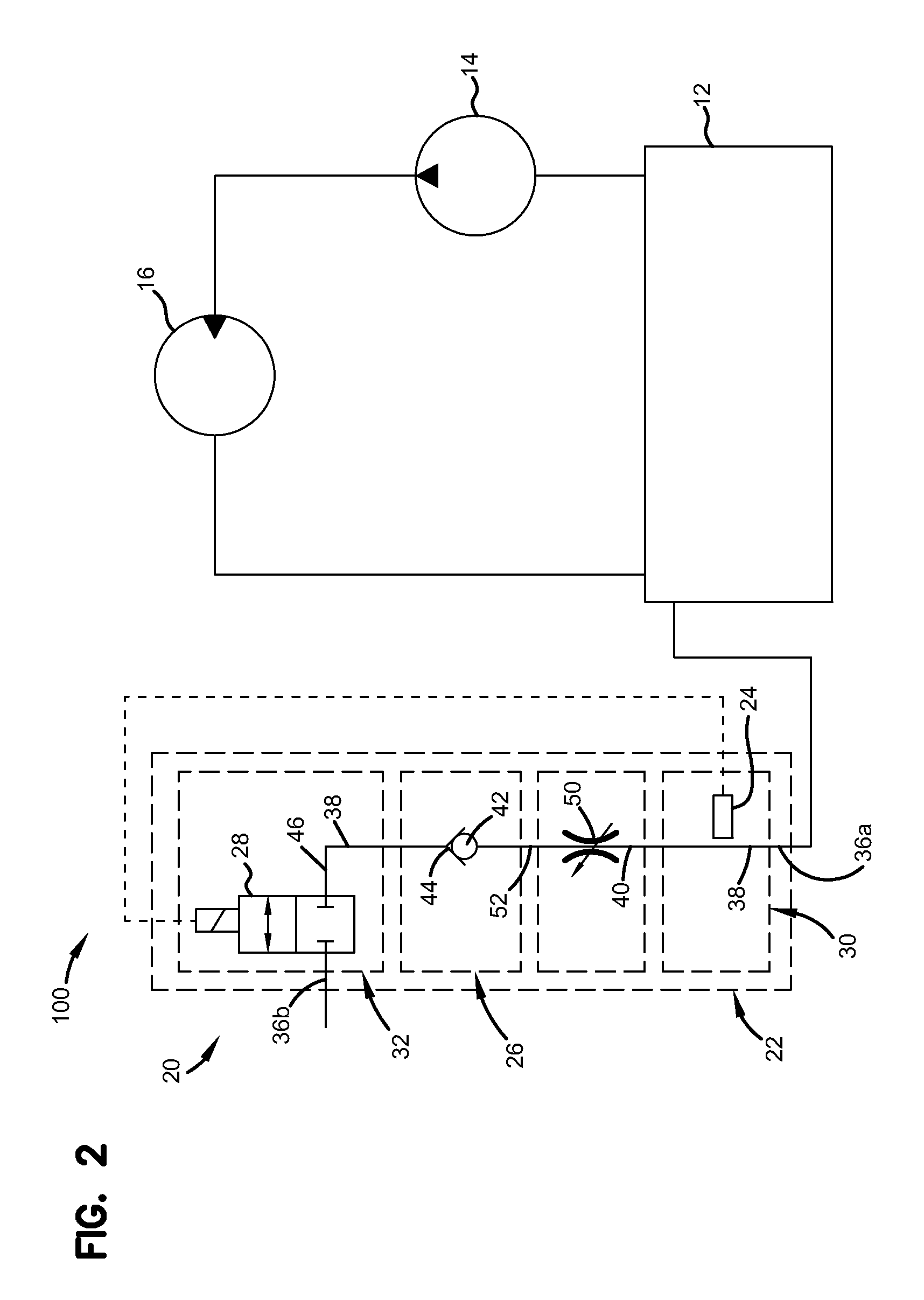
[0014]FIG. 1 depicts a schematic representation of one embodiment of a simplified hydraulic system, generally designated 10. The hydraulic system 10 includes a reservoir 12, a pump 14, an actuator 16, which is shown herein as a motor, and a bleed valve assembly, generally designated 20. In one embodiment, the hydraulic system 10 is disposed on an aerospace application such as an aircraft. The reservoir 12 provides a receptacle for holding fluid for the hydraulic system 10. ...


PUM


Abstract

A bleed valve assembly includes a control assembly having a fluid inlet, a fluid outlet and a passageway in fluid communication with the fluid inlet and the fluid outlet. A fluid inlet air pressure is greater than a fluid outlet air pressure. An electromechanical valve is disposed in the control assembly and provides selective fluid communication between the passageway and the fluid outlet. A valve assembly is disposed in the passageway of the control assembly and prevents fluid communication of non-gaseous fluid between the fluid inlet and the fluid outlet. The valve assembly includes a float member and a float seat. A flow restrictor is in fluidic communication with the passageway and is configured to maintain a pressure within the assembly such that a change in a gaseous fluid pressure across the valve assembly is insufficient to close the valve assembly.

Description

INTRODUCTION[0001]The versatility and flexibility of hydraulic systems give them many advantages over other methods of transmitting power. However, like many power systems, proper care of the hydraulic system must be taken in order to prevent problems.[0002]A typical problem that can occur in hydraulic systems is aeration. Aeration in hydraulic systems is commonly caused by air entering the hydraulic system through a leak in an inlet line or as a result of a low fluid level in the reservoir. If the air in the fluid of the hydraulic system is not released, the air will implode against components of the pump. This implosion of air releases large amounts of energy that can result in damage to the pump, which over time can result in premature failure of the pump.[0003]While prior art air-vent valves have been used to release air in the hydraulic system, such valves do not protect against hydraulic leakage from the valve as a result of a valve component failure. Leakage in hydraulic syst...

Claims


Application Information

Patent Timeline
IPC IPC(8): F16K24/04F15B21/044
CPCF16K24/042F15B21/044F15B2211/40515F15B2211/411F15B2211/426F15B2211/6303F15B2211/655Y10T137/86292
Inventor SKINNER, JEFFREY, D.
Owner EATON CORP
Why Eureka
Try Eureka