
Camshaft phaser

A technology of camshaft and phaser, which is applied in the field of vane camshaft phaser and camshaft phaser of vane camshaft phaser, and can solve the problems of complex and difficult to realize camshaft phaser

Inactive Publication Date: 2019-03-05
DELPHI TECH IP LTD
View PDF7 Cites 1 Cited by
  • Summary
  • Abstract
  • Description
  • Claims
  • Application Information

AI Technical Summary

Problems solved by technology

However, such known camshaft phasers may be too complex to implement

Method used


Image

  • Camshaft phaser
  • Camshaft phaser
  • Camshaft phaser

Examples


Embodiment Construction

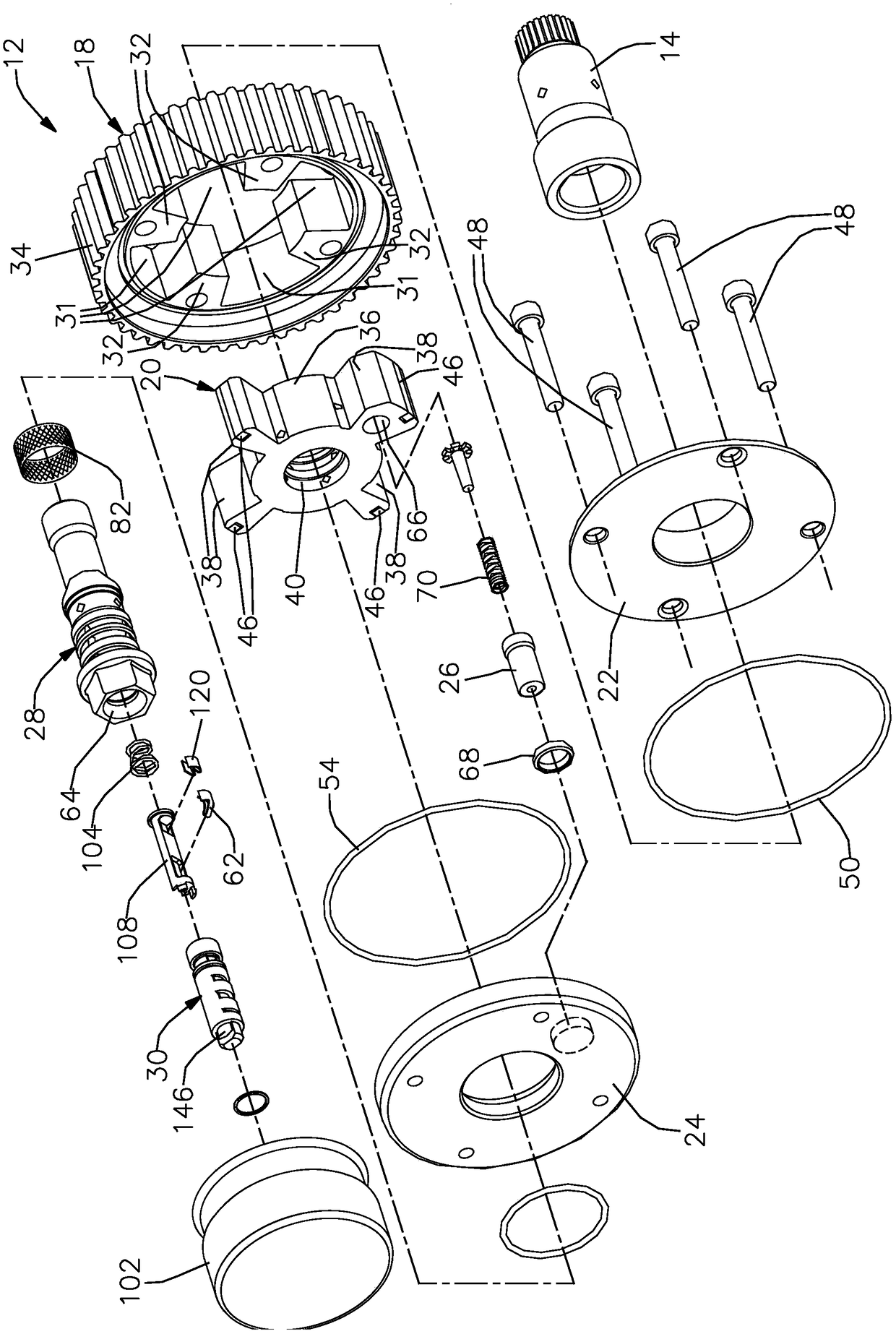
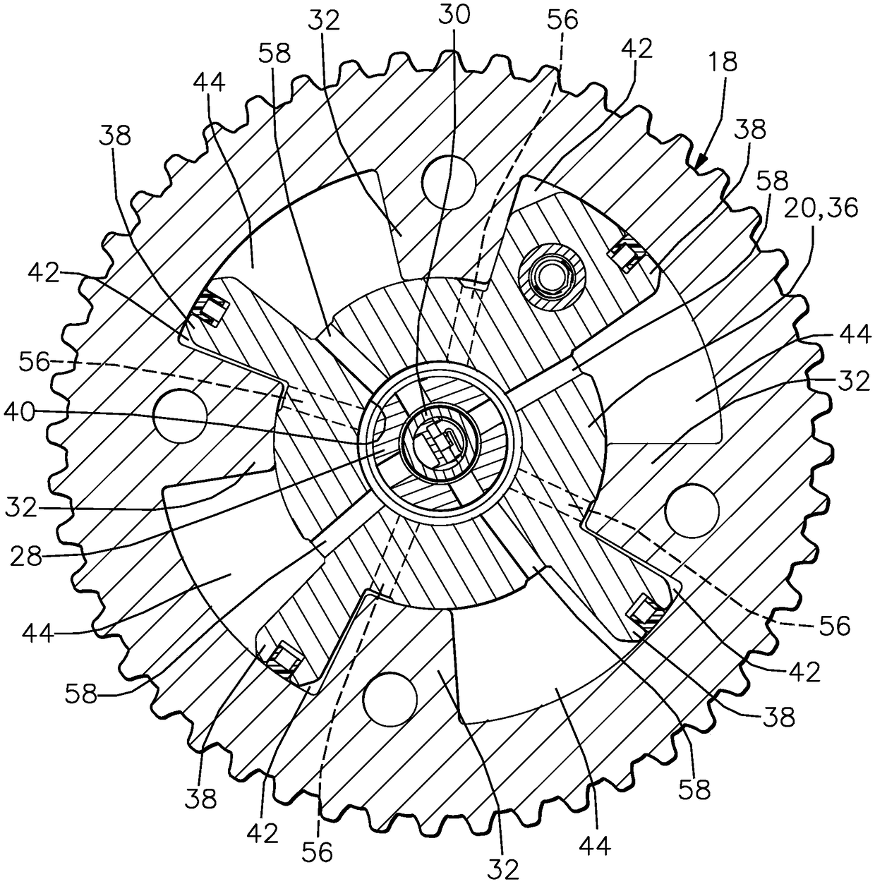
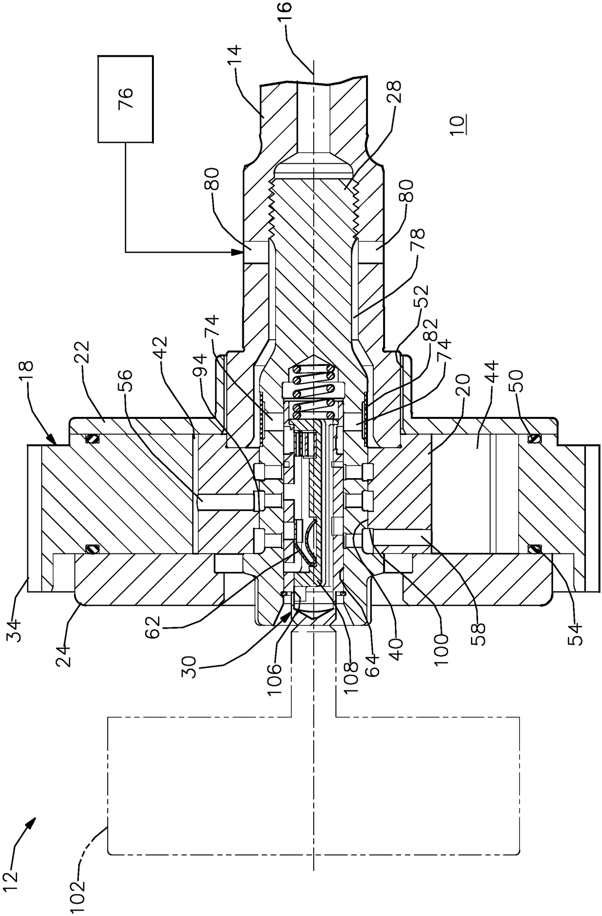
[0022] According to the preferred embodiment of the present invention and with reference to Figure 1-Figure 4 , shows an internal combustion engine 10 including a camshaft phaser 12 . The internal combustion engine 10 also includes a camshaft 14 rotatable about a camshaft axis 16 based on a rotational input from a crankshaft (also not shown) driven by a plurality of reciprocating pistons (not shown) and a belt. As is well known in internal combustion engine technology, the camshaft 14 imparts a valve lift and closing motion to the intake and / or exhaust valves (not shown) as it rotates. Camshaft phaser 12 allows timing between the crankshaft and camshaft 14 to be varied. In this way, opening and closing of the intake and / or exhaust valves can be advanced or retarded to achieve desired engine performance.

[0023] The camshaft phaser 12 generally includes: a stator 18, which serves as an input member; a rotor 20, which is coaxially disposed within the stator 18, and which ser...


PUM


Abstract

A camshaft phaser (12) includes an input member (18); an output member (20) defining an advance chamber (42) and a retard chamber (44) with the input member (18); a supply passage (78); a vent passage(146); and a valve spool (30) within the output member (20) which is moveable between a first and second position. The first position prevents communication between the advance chamber (42) and the vent passage (146), prevents communication between the retard chamber (44) and the vent passage (146), and allows oil to flow from one of the advance chamber (42) and the retard chamber (44) to the other of the advance chamber and the retard chamber. The second position provides communication between the vent passage and one of the advance chamber (42) and the retard chamber (44), prevents communication between the vent passage and the other of the advance chamber and the retard chamber, and provides communication between the supply passage and the other of the advance chamber and the retard chamber.

Description

[0001] Cross references to related patent applications [0002] This patent application claims priority to U.S. Provisional Patent Application Serial No. 62 / 552,985, filed August 31, 2017, the disclosure of which is incorporated herein by reference in its entirety. technical field [0003] The present invention relates to a camshaft phaser, which is used to change the phase relationship between the crankshaft and the camshaft in an internal combustion engine; more specifically, it relates to a camshaft phaser of a vane type camshaft phaser; further specifically In other words, it relates to a vane cam phaser capable of switching from actuating the camshaft phaser using only torque reversal of the camshaft to actuating the camshaft phaser using pressurized oil from at least an external oil source. Background technique [0004] A typical vane camshaft phaser used to vary the phase relationship between the crankshaft and camshaft of an internal combustion engine typically inclu...

Claims


Application Information

Patent Timeline
Patent Type & Authority Applications(China)
IPC IPC(8): F01L1/344
CPCF01L1/3442F01L2001/3443F01L2001/34459F01L1/34409F01L2001/34433F01L2001/3444F01L2001/34469F01L2250/04F01L2301/00
Inventor K·J·小霍尔蒂纳D·C·普雷斯科特
Owner DELPHI TECH IP LTD
Learn More