Control system for rotary electric machine and method for controlling the same

A technology for controlling systems and rotating electrical machines, which is applied in the field of changing the effective magnetic flux of the rotor, and can solve the problems of increasing the size and cost of rotating electrical machines

Inactive Publication Date: 2015-11-18
TOYOTA JIDOSHA KK
View PDF7 Cites 2 Cited by
  • Summary
  • Abstract
  • Description
  • Claims
  • Application Information

AI Technical Summary

Problems solved by technology

Therefore, this leads to an increase in the size and cost of the rotating electrical machine

Method used


Image

  • Control system for rotary electric machine and method for controlling the same
  • Control system for rotary electric machine and method for controlling the same
  • Control system for rotary electric machine and method for controlling the same

Examples


Embodiment Construction

[0038] Embodiments of the present invention will be explained below with reference to the drawings. In the following, the same components are described using the same reference numerals in all figures.

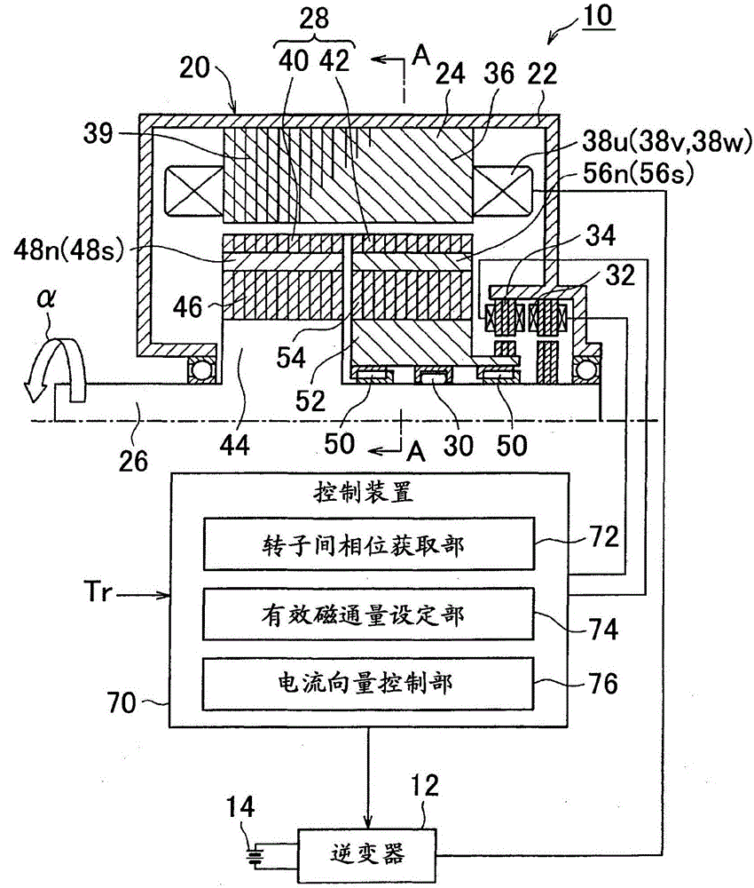
[0039] [first embodiment] figure 1 A rotating electrical machine control system 10 according to a first embodiment of the present invention is shown. The rotary electric machine control system 10 is equipped with a rotary electric machine 20 , an inverter 12 serving as a drive circuit, an electric storage device 14 serving as a power source, and a controller 70 . The rotating electrical machine control system 10 is mounted to an electric vehicle such as a hybrid vehicle, an electric vehicle, or a fuel cell vehicle, and is used to drive wheels (not shown) using the rotating electrical machine 20 as an electric motor. The rotary electric machine 20 can be used as a generator, a motor, or a motor-generator having both functions of a motor and a generator.

[0040]The rotary el...


PUM


Abstract

A rotary electric machine control system (10) includes a controller (70), and a rotor (28) including a first rotor element (40) and a second rotor element (42) which are rotatable inside of the stator (24) and disposed to be separated from each other in axial direction. The first rotor element (40) includes a first magnet and is fixed to a rotary shaft (26). The second rotor element (42) includes a second magnet, and is rotatably provided to the rotary shaft (26). The controller (70) performs vector control of the stator coil current for transition of an inter-rotor phase, a relative phase difference of the second rotor element (42) in relation to the first rotor element (40).

Description

technical field [0001] The present invention relates to a control system of a rotating electric machine and a method of controlling the control system, and also to a technique for varying the effective magnetic flux of a rotor. Background technique [0002] A magnetic flux variable rotating electrical machine is known, as described in Japanese Patent Application Publication No. 2010-154699 (JP2010-154699A). The rotating electric machine described in JP2010-154699A is configured to change the rotor that contributes to the torque by changing the positional relationship of the rotor equipped with two magnets by means of an actuator in response to a change in the phase relationship between the two rotors Magnetic flux in which two magnets are arranged separated in the direction of the axis of rotation. [0003] The flux variable type rotating electric machine described in JP2010-154699A requires an actuator serving as a dedicated drive source to change the effective magnetic fl...

Claims


Application Information

Patent Timeline
Patent Type & Authority Applications(China)
IPC IPC(8): H02K21/02H02K29/12H02P21/00H02P21/06H02P21/10H02P21/12H02P21/22H02P25/026H02P27/04
CPCH02P21/00H02K21/029H02K29/12H02P21/22H02K7/108H02P6/14
Inventor 三浦彻也柳生泰秀门田贵宪
Owner TOYOTA JIDOSHA KK
Why Eureka
Try Eureka