Stator core coil axially adjustable brushless permanent magnet motor and its control system
A technology of stator iron core and permanent magnet motor, applied in control system, motor control, model/simulation for control purposes, etc., can solve the problems of increasing the volume and cost of the car, large fluctuation of the generator voltage, and reducing the weight of the car.
- Summary
- Abstract
- Description
- Claims
- Application Information
AI Technical Summary
Problems solved by technology
Method used
Image
Examples
Embodiment 1
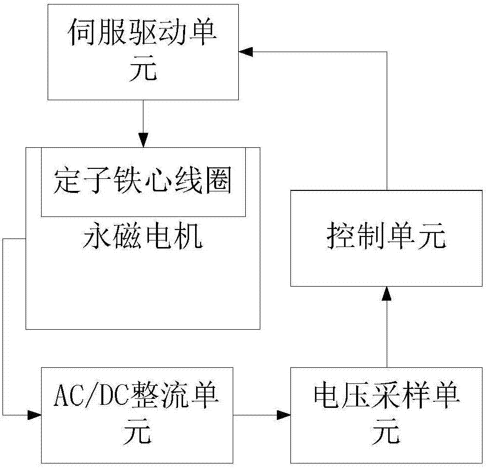
[0033] The embodiment of the present invention provides a brushless permanent magnet motor control system with axially adjustable stator core coil, such as figure 1 As shown, it includes: a permanent magnet motor, an AC / DC rectifier unit, a control unit, and a voltage sampling unit.
[0034] The permanent magnet motor is a brushless permanent magnet motor with axially adjustable stator core coils, which includes: a motor housing, a permanent magnet rotor rotatably installed in the motor housing, and a stator core composed of coils wound on the core Coil, the stator core coil can be axially moved on the inner wall of the motor housing, and the stator core coil is driven by a driving device to move axially along the inner wall of the motor housing to change the effective magnetic flux on the coil winding relative to the permanent magnet rotor . It can be understood that the manner in which the coils are wound on the iron core to form the stator core coils can be completed by th...
Embodiment 2
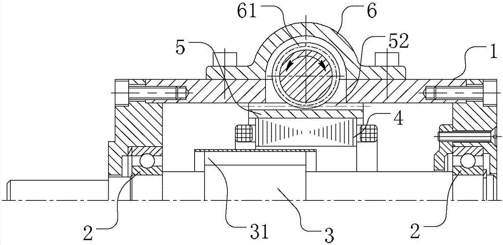
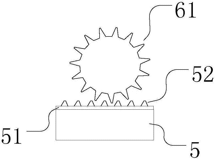
[0053] The embodiment of the present invention also provides a stator core coil axially adjustable motor control system, which differs from that in Embodiment 1 above in that the structure of the motor is slightly improved. Such as Figure 6 and Figure 7 As shown, in the embodiment of the present invention, the fixing device is still a hollow guide cylinder 5 with both ends open, and the stator core coil 4 is embedded in the hollow guide cylinder 5 and moves integrally with the hollow guide cylinder 5. The difference is that the drive connection part is The axial rack 52 arranged on the outer wall of the hollow guide cylinder does not need to increase the guide protrusions as in Embodiment 1, and only the tooth grooves are arranged axially on the outer wall of the hollow guide cylinder; It is a drive gear meshing with the axial rack.
[0054] In the embodiment of the present invention, the driving device drives the hollow guide cylinder to move. The standard name of this mo...
Embodiment 3
[0059] Such as Figure 8 As shown, the embodiment of the present invention is based on the stator core coil axially adjustable brushless permanent magnet motor control system in the above embodiment 1, an electronic commutator and a line switching unit are added, and the permanent magnet motor is connected through its phase line The line switching unit is also connected to the electronic commutator and the AC / DC rectifier unit respectively. The line switching unit receives the control signal from the control unit and selects to connect the permanent magnet motor and the electronic commutator or to connect the permanent magnet motor and the AC / DC rectifier. DC rectification unit.
[0060] Specific as Figure 9 As shown, the switching unit includes a first terminal J1 for connecting the phase line of the permanent magnet motor, a second terminal J2 for connecting the electronic commutator, and a third terminal for connecting the AC / DC rectifier unit Terminal J3, the first term...
PUM
 Abstract
Description
Claims
Application Information
 - R&D
- Intellectual Property
- Life Sciences
- Materials
- Tech Scout
- Unparalleled Data Quality
- Higher Quality Content
- 60% Fewer Hallucinations
Browse by: Latest US Patents, China's latest patents, Technical Efficacy Thesaurus, Application Domain, Technology Topic, Popular Technical Reports.
© 2025 PatSnap. All rights reserved.Legal|Privacy policy|Modern Slavery Act Transparency Statement|Sitemap|About US| Contact US: help@patsnap.com


