
Self-switching pressure-stabilizing three-way shunt

A shunt and self-switching technology, which is applied in the direction of multi-way valves, engine components, mechanical equipment, etc., can solve the problems of inconvenient control, damage to the water inlet flow, etc., and achieve good voltage stabilization, good flow effect, and less damage to the water inlet flow The effect of control

Inactive Publication Date: 2013-02-06
MAIN PLAN NINGBO BATHROOM COLLECTIONS
View PDF6 Cites 3 Cited by
  • Summary
  • Abstract
  • Description
  • Claims
  • Application Information

AI Technical Summary

Problems solved by technology

[0003] The purpose of the present invention is to overcome the common three-way joints used for water inlet to transfer and divert water. When the water inlet water pressure is unstable or the water pressure is too high, the water parts in water devices such as showers and toilets are easy to cause damage and water diversion. To control the inconvenience, provide a self-switching voltage regulator that can stabilize the water pressure when the water pressure is unstable or too high, so that the water parts in water devices such as showers and toilets are not easy to be damaged and the water diversion control is convenient. Three-way splitter

Method used


Image

  • Self-switching pressure-stabilizing three-way shunt

Examples


Embodiment Construction

[0014] The present invention will be further described below in conjunction with the accompanying drawings.

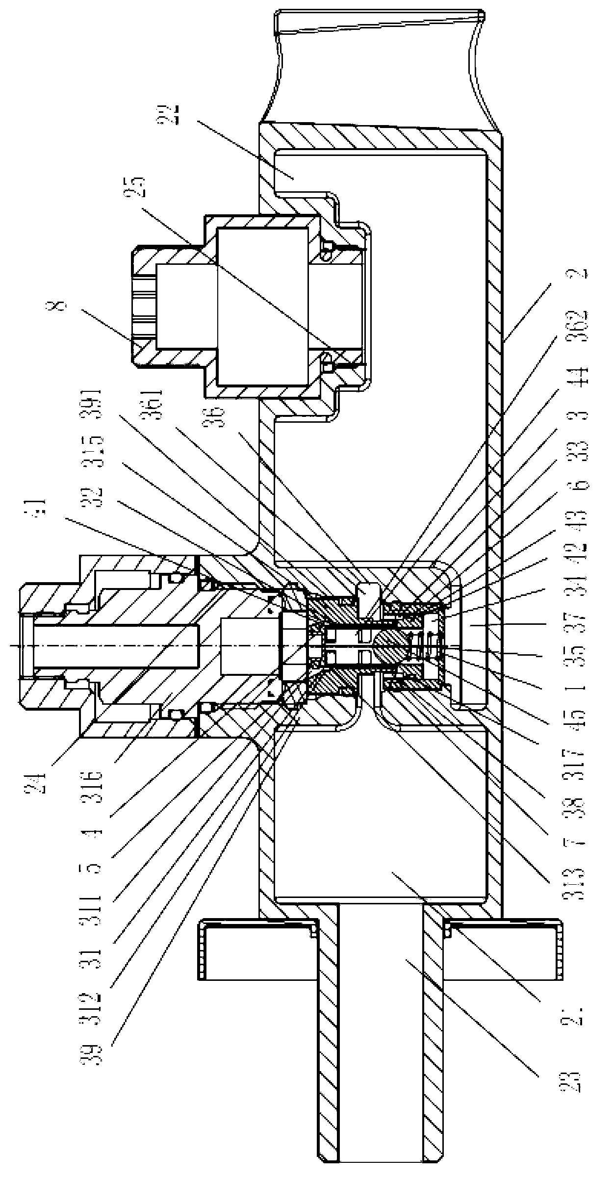
[0015] as attached figure 1 Shown: a self-switching stabilized three-way flow divider, including a valve body 2, a valve seat 3 located in the middle of the valve body 2 and dividing the valve body 2 into a front chamber 21 and a rear chamber 22, an inner valve core 4 and a compression spring 1; the inner spool 4 includes a main section 41 connected in sequence, a transition section 42 with a diameter greater than the diameter of the main section 41, and a blocking section 43 with a diameter greater than the diameter of the transition section 42; the inner spool 4 has a middle hole 44, and the middle The middle part of the hole 44 has a spacer 45; the valve seat 3 has an upper hole 31, a main hole 32, a transition hole 33, a blocking hole 34 and a lower hole 35 in sequence along the radial direction of the valve body 2; the main hole 32 and the blocking hole The block...


PUM

PropertyMeasurementUnit
Radial sizeaaaaaaaaaa

Abstract

The invention relates to the field of water devices, and aims to provide a self-switching pressure-stabilizing three-way shunt which is capable of stabilizing the pressure to prevent the water devices such as a shower head, a closestool and the like from being damaged easily and is convenient for control of water flow shunting. The self-switching pressure-stabilizing three-way shunt comprises a valve body, a valve base for dividing the valve body into a front chamber and a rear chamber, an inner valve core and a compressed spring, wherein the inner valve core comprises a main section, a transit section and a stopping section which are connected sequentially; a middle hole is formed in the valve core; a spacer block is arranged at the middle part of the middle hole; an upper hole, a main hole, a transit hole, a stopping hole and a lower hole are formed in the valve base sequentially in the radial direction of the valve body; an upper groove communicated with the front chamber is formed in the middle part of the lateral side of the valve base; a lower groove communicated with the lower hole and the rear chamber respectively is formed in the lower end of the valve base; a water intake hole communicated with the transit hole is formed in the lower side surface of the upper groove; two ends of the compressed spring are in contact with the lower end surface of the stopping hole and the lower end surface of the spacer block respectively; a first sealing ring is arranged at the upper part of the main section; and a second sealing ring is arranged at the lower part of the transit section.

Description

technical field [0001] The present invention relates to the field of water devices, in particular to an automatic device capable of stabilizing the water pressure when the water inlet pressure is unstable or too high so that the water parts in water devices such as showers and toilets are not easily damaged and the flow control of the water inlet is convenient. Switch the regulated three-way shunt. Background technique [0002] The bathroom has multiple water devices such as showers and flush toilets, and the water inlet is often diverted by a three-way joint; when the water pressure of the water inlet is unstable or the water pressure is too high, the water parts in the water devices such as the shower and toilet are easy to cause damage and inconvenient control of water inlet diversion; therefore, it is necessary to design a method that can stabilize the pressure when the water inlet water pressure is unstable or too high so that the water parts in water devices such as sh...

Claims


Application Information

Patent Timeline
IPC IPC(8): F16K11/02
Inventor 施清海
Owner MAIN PLAN NINGBO BATHROOM COLLECTIONS
Learn More