Staggered parallel DC-DC converter with high step-down ratio

A DC-DC, high step-down technology, applied in the direction of output power conversion device, DC power input conversion to DC power output, instruments, etc., can solve the problem that it is difficult to meet the duty cycle, efficiency, heat dissipation, and step-down ratio. Problems such as boosting and poor voltage regulation ability, to achieve the effect of good voltage regulation ability, low output ripple, and low input current ripple

Active Publication Date: 2019-11-15
XI AN JIAOTONG UNIV
View PDF2 Cites 0 Cited by
  • Summary
  • Abstract
  • Description
  • Claims
  • Application Information

AI Technical Summary

Problems solved by technology

[0003] The traditional Buck converter has good voltage regulation ability, but the step-down ratio is not high, the input current is intermittent, and it is difficult to meet the requirements of duty cycle, efficiency and heat dissipation in low-voltage and high-current applications.
The interleaved parallel structure is a commonly used technical means in the DC-DC converter topology. The interleaved parallel converter has many advantages, such as reducing the output current ripple, reducing the inductance value required by the circuit, and easy to achieve high frequency, etc., but it is different from the traditional Compared with the Buck converter, the step-down ratio has not been improved
In addition, introducing switched capacitor units into the topology is also a common method to improve traditional converters. Switched capacitor converters can achieve high step-down ratios, high power density, small size, and are easy to integrate, but have poor voltage regulation capabilities

Method used


Image

  • Staggered parallel DC-DC converter with high step-down ratio
  • Staggered parallel DC-DC converter with high step-down ratio
  • Staggered parallel DC-DC converter with high step-down ratio

Examples


Embodiment Construction

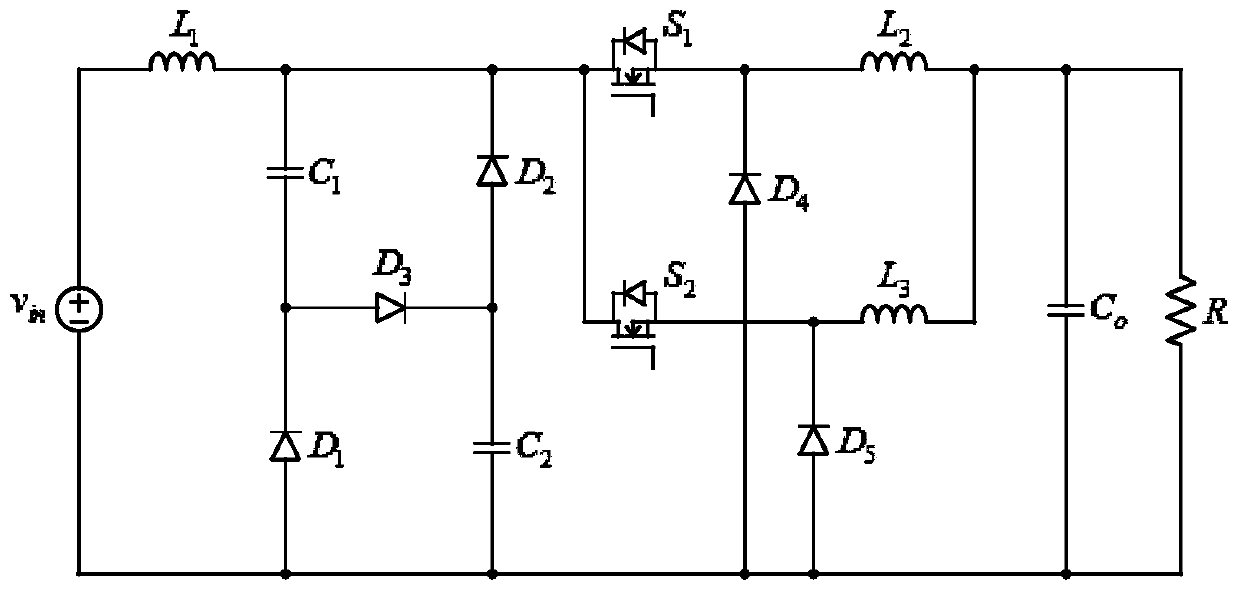
[0030] The present invention is described in further detail below in conjunction with accompanying drawing:

[0031] refer to figure 1 , the high step-down ratio interleaved parallel DC-DC converter of the present invention includes a power supply V in , the first capacitance C 1 , the second capacitance C 2 , the first inductance L 3 , the second inductance L 2 , the first switch tube S 1 , the second switch tube S 2 , the first diode D 1 , the second diode D 2 , the third diode D 3 , the fourth diode D 4 , the fifth diode D 5 and load resistance R; power supply V in The positive pole of the first capacitor C 1 One end of the second diode D 2The negative pole of the first switch tube S 1 One end of and the second switch tube S 2 One end is connected, the first capacitor C 1 The other end of the third diode D 3 The anode and the first diode D 1 The cathode of the second diode D is connected 2 The anode of the third diode D 3 The negative pole and the second...


PUM


Abstract

The invention discloses a staggered parallel DC-DC converter with a high step-down ratio. The positive electrode of a power supply is connected with one end of a first capacitor, the negative electrode of a second diode, one end of a first switch transistor and one end of a second switch transistor; the other end of the first capacitor is connected with the positive electrode of a third diode andthe negative electrode of a first diode; the positive electrode of the second diode is connected with the negative electrode of the third diode and one end of a second capacitor; the other end of a first switch transistor is connected with one end of a second inductor and the negative electrode of a fourth diode; the other end of the second switch transistor is connected with one end of the firstinductor and the negative electrode of a fifth diode; the other end of the first inductor is connected with the other end of the second inductor and one end of a load resistor; and the negative electrode of the power supply is connected with the other end of the second capacitor, the other end of the load resistor, the positive electrode of the fifth diode and the positive electrode of the first diode. The converter has the characteristics of a high step-down ratio, low output ripples, continuous input current and good voltage regulation ability.

Description

technical field [0001] The invention belongs to the design field of power electronic DC converters, and relates to an interleaved parallel DC-DC converter with a high step-down ratio. Background technique [0002] With the rapid development of industrial technology in recent years, the importance of power electronics technology and related equipment has become increasingly prominent. Among them, DC-DC converters are widely used in power grids, automobiles, rail transit, biomedicine and communication systems. In recent years, in order to pursue development trends such as high efficiency, high power density, and low cost, applications such as data centers, automotive electronics, and distributed energy systems have gradually favored higher voltage power architectures, such as replacing the traditional 12V DC with 48V Bus voltage, but many terminal equipment still maintain low voltage input requirements. It has important practical significance and application value to study DC...

Claims


Application Information

Patent Timeline
Patent Type & Authority Applications(China)
IPC IPC(8): H02M3/158H02M1/14
CPCH02M1/14H02M3/1584H02M3/1586
Inventor 周展羽王发强
Owner XI AN JIAOTONG UNIV
Why Eureka
Try Eureka