
Voltage Regulator

A technology of voltage regulator and input capacitor, applied in the direction of regulating electrical variables, control/regulating systems, instruments, etc., can solve the problems of voltage regulation that cannot achieve variable ratio, and achieve the effect of simple structure, small volume and high power density

Active Publication Date: 2019-02-22
NANJING SILERGY SEMICON TECH CO LTD
View PDF5 Cites 0 Cited by
  • Summary
  • Abstract
  • Description
  • Claims
  • Application Information

AI Technical Summary

Problems solved by technology

[0003] However, the existing architecture of switched capacitor converters cannot realize the voltage regulation of ratio

Method used


Image

  • Voltage Regulator
  • Voltage Regulator
  • Voltage Regulator

Examples


Embodiment Construction

[0046] The present invention is described below based on examples, but the present invention is not limited to these examples. In the following detailed description of the invention, some specific details are set forth in detail. The present invention can be fully understood by those skilled in the art without the description of these detailed parts. In order not to obscure the essence of the present invention, well-known methods, procedures, procedures, components and circuits have not been described in detail.

[0047] Additionally, those of ordinary skill in the art will appreciate that the drawings provided herein are for illustrative purposes and are not necessarily drawn to scale.

[0048] Meanwhile, it should be understood that in the following description, "circuit" refers to a conductive loop formed by at least one element or sub-circuit through electrical connection or electromagnetic connection. When an element or circuit is said to be "connected to" another eleme...


PUM


Abstract

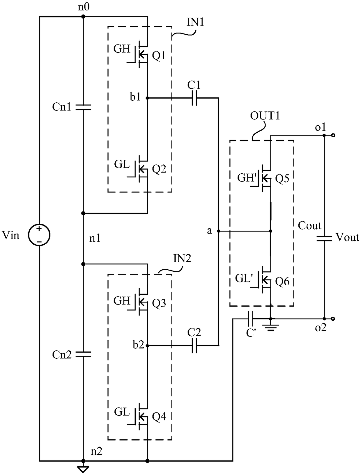
Disclosed is a voltage regulator, N input circuits are formed through N input capacitors and corresponding N input switch units, and at the same time, output circuits are formed through output switch units, and the N input circuits are respectively connected through N energy storage capacitors to the output circuit. Power conversion is realized by controlling the input switch unit and the output switch unit to perform state switching, and controlling the energy storage capacitor and the input capacitor to perform charging and discharging operations. The step-down ratio of the voltage regulator can be set by changing the input circuit and the number of storage capacitors. Thus, a higher step-down ratio can be achieved with a smaller volume. The voltage regulator of the embodiment of the present invention has simple structure and high power density.

Description

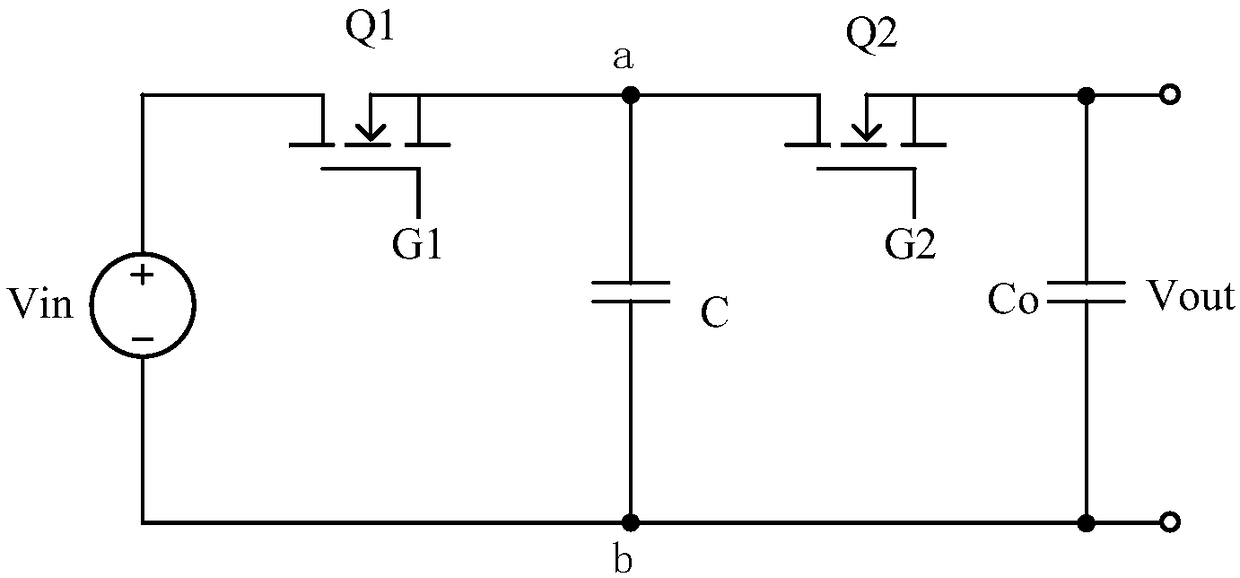
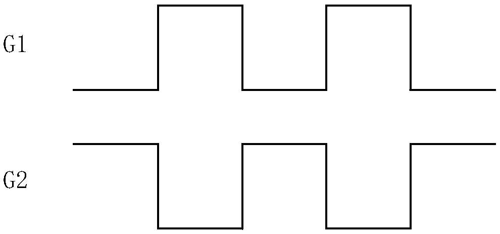
technical field [0001] The present invention relates to power electronics technology, in particular to a voltage regulator. Background technique [0002] Switched capacitor voltage regulators control the charging and discharging of capacitors through switches to achieve voltage conversion. Existing switched capacitor voltage regulators such as figure 1 As shown, the input port is applied with an input voltage Vin. The switch Q1 is connected between the terminal a of the capacitor C and the first terminal i of the voltage input port, and is turned on or off under the control of the control signal G1. The switch Q2 is connected between the terminal a of the capacitor C and the first terminal of the output port, and is turned on or off under the control of the control signal G2. Wherein, the control signals G1 and G2 are inverted, that is, when the control signal G1 is at a high level, the control signal G2 is at a low level. Meanwhile, the terminal b of the capacitor C is ...

Claims


Application Information

Patent Timeline
Patent Type & Authority Patents(China)
IPC IPC(8): G05F3/10
CPCG05F3/10H02M3/07H02M1/0095
Inventor 张望赵晨
Owner NANJING SILERGY SEMICON TECH CO LTD
Learn More