
A kind of direct current converter and its control method
A technology of DC converter and control method, which is applied in the direction of converting DC power input to DC power output, converting irreversible DC power input into AC power output, control/regulation system, etc., and can solve problems such as difficult zero-voltage turn-on of switches , to achieve the effect of reducing the resonant current, improving the conversion efficiency, and improving the conversion efficiency
- Summary
- Abstract
- Description
- Claims
- Application Information
AI Technical Summary
Problems solved by technology
Method used
Image

Examples
Embodiment Construction
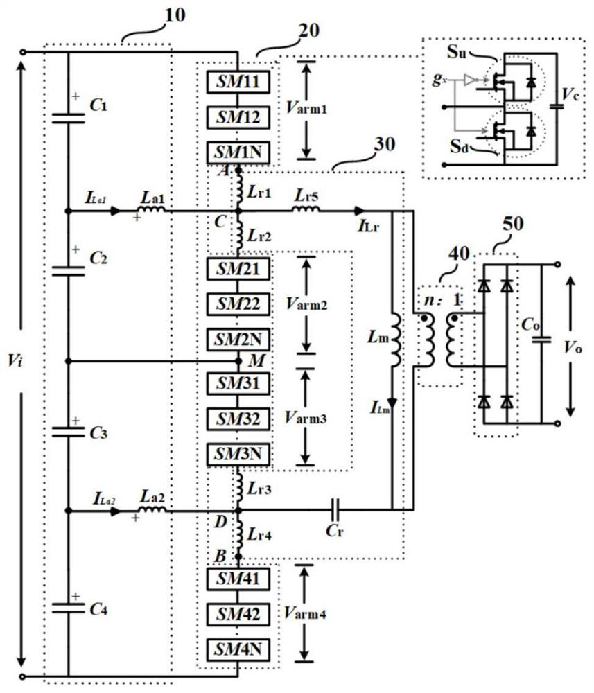
[0032] The topological structure of the combined resonant converter proposed by the present invention is as follows: figure 1 As shown, it includes a soft-switching network 10 , a combined circuit 20 , a resonant network 30 , a transformer 40 , and a rectifier 50 . V i , V o are the converter input and output voltages, respectively. Each bridge arm contains N sub-modules, and each sub-module has the same structure, including an upper switch tube S u , a lower switch tube S d and a capacitor, the upper switch tube is connected in series with the lower switch tube and then connected in parallel with the capacitor, the sub-module drives the signal g x It is the driving signal of the lower switch tube, and the duty ratios of the upper and lower switch tubes are complementary and will not be turned on at the same time. I Lr , I Lm are the resonant current and the excitation current, respectively.
[0033] The soft-switching network consists of capacitor C 1 , C 2 , C 3 ,...
PUM
 Abstract
Description
Claims
Application Information