
Multiple Winding Integrated Transformers

a transformer and integrated technology, applied in the field of multi-winding transformers in power electronic systems, can solve the problems of difficult commercial manufacturing, inconvenient use, and the inability to use a three-winding transformer with a center leg twice, and achieve the effect of high step-down ratios

Pending Publication Date: 2022-06-02
UNIV OF MARYLAND
View PDF0 Cites 2 Cited by
  • Summary
  • Abstract
  • Description
  • Claims
  • Application Information

AI Technical Summary

Benefits of technology

The present patent relates to a set of universal design structures and design ideas that can be applied to any kind of multi-port magnetically integrated power electronic system with or without integrated leakage inductances. The patent presents a new three-winding planar transformer design that enables two output voltage levels with high step-down ratios. It also discusses a global transformer optimization approach that considers various factors such as magnetizing and leakage inductances, core and winding losses, and parasitic capacitances. Overall, the patent provides a truly extendable generalized N-port multi-winding integrated leakage transformer.

Problems solved by technology

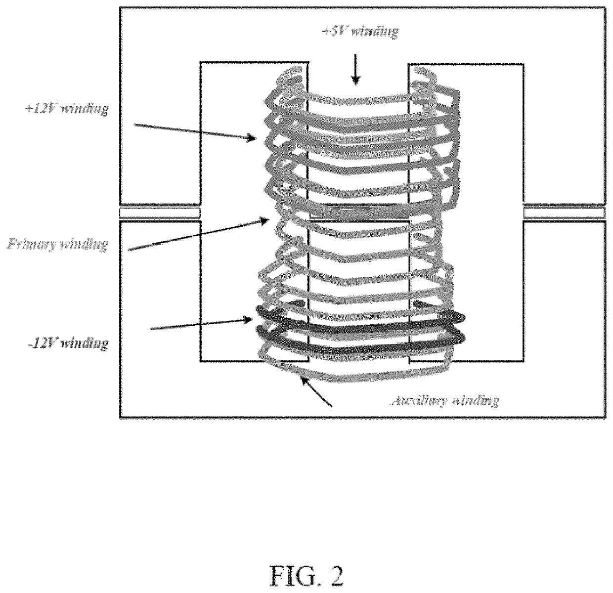
The traditional approach of using a three-winding transformer with a center leg twice the width of the outer legs, see Xusheng Chen and S. S. Venkata; and S. Baek and S. Bhattacharya, is not suitable in this case due to the inherently unbalanced flux distribution of the core.
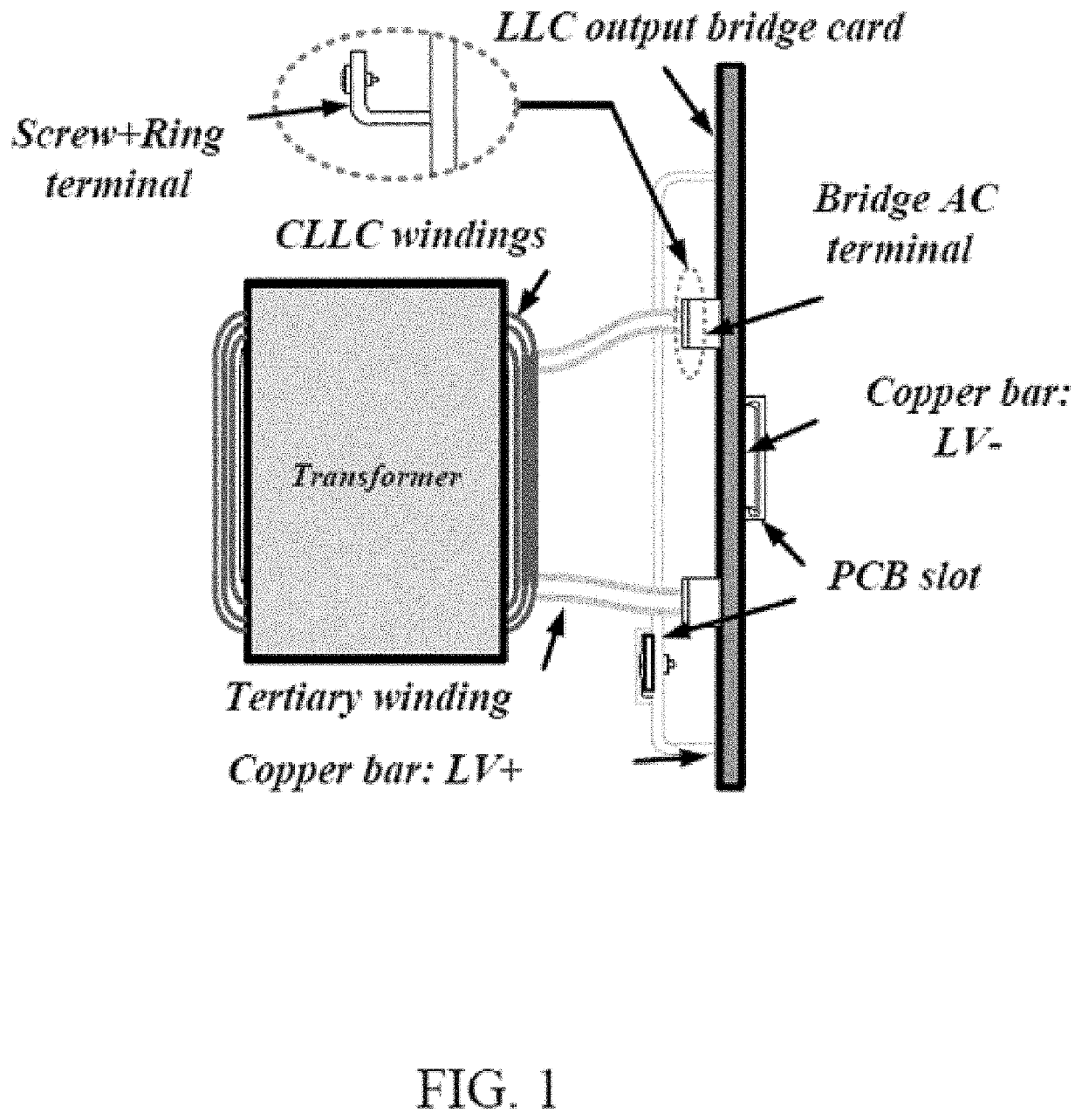
The tertiary winding is made of copper bar and needs massive labor, making it difficult for commercial manufacturing.
Moreover, the implementation of a standard EE core limits the simultaneous charging function due to high winding loss.
However, in this design, the leakage inductance is not large enough to account for the required shim inductance in phase-shifted based converter (i.e., dual-active-bridge converter) and resonant converter (i.e., CLLC converter).
Moreover, since the system is operated at low power, the analysis on parasitic capacitances with the interleaved winding structure is out of the scope.
However, four quadrants structure limit the maximum current rating of the system and the thermal dissipation capability.
Moreover, this winding structure may cause a higher and uncontrollable leakage inductance than that of a traditional transformer.

Method used


Image

  • Multiple Winding Integrated Transformers
  • Multiple Winding Integrated Transformers
  • Multiple Winding Integrated Transformers

Examples


Embodiment Construction

[0079]This invention was made with government support under IIP1602012 awarded by the National Science Foundation. The government has certain rights in the invention.

[0080]Many example embodiments are described herein that realize electromagnetic integration by means of different core and winding configurations, which is highly desirable in several applications, including but not limited to simultaneous charging of EVs and multi-port energy router systems. They can be implemented in both single-phase and three-phase systems. The core geometry selections are determined based on the various application requirements, i.e. power rating, weight, volume, and cost. For instance, EE-shape may be a good candidate for certain applications as it provides enough space for the three-winding structure. Besides, UU-shape, EI-shape or PQ-shape can also be utilized with the customized dimensions. There are variations in the winding configurations, including conductor type, arrangement, thickness, an...


PUM

PropertyMeasurementUnit
dimensionsaaaaaaaaaa
magneticaaaaaaaaaa
voltageaaaaaaaaaa

Abstract

A set of multi-winding transformer designs that achieve leakage integration in multi-port power electronics systems is presented. The magnetic design structures are extendable to realize an N-port multi-winding transformer with or without leakage inductance integration, that interfaces different voltage levels (high-voltage and / or low-voltage) with galvanic isolation. The disclosed designs enable: (i) reduced number of discrete magnetic components (ii) high efficiency and high power density; (iii) reduced transformer parasitic capacitances. Furthermore, a global transformer optimization approach that considers magnetizing and leakage inductances, core and winding losses, and parasitic capacitances is presented to systemize the sophisticated multi-winding integrated leakage transformer design process.

Description

CROSS-REFERENCE TO RELATED APPLICATIONS[0001]This application claims the benefit of U.S. Provisional Patent Application No. 63 / 119,615, filed Nov. 30, 2020, which is incorporated by reference herein in its entirety for all purposes.Statement of Government SupportTECHNICAL FIELD[0002]The disclosure relates to multi-winding transformers in power electronic systems.BACKGROUND AND DESCRIPTION OF THE RELATED ART[0003]There are several power electronic parts / systems that significantly benefit from magnetic integration of electrical ports that interface different voltage levels. Magnetic integration can be achieved through multi-winding transformers or coupled inductors. This disclosure addresses magnetic integration through multi-winding transformers with various core / winding geometries and structures. There are several target applications for such multi-winding / multi-port transformers, including, but not limited to, electric vehicle (EV) charging systems, data center power distribution, ...

Claims


Application Information

Patent Timeline
Patent Type & Authority Applications(United States)
IPC IPC(8): H01F27/28H01F27/24H05K1/16
CPCH01F27/2804H01F2027/2809H05K1/165H01F27/24H01F2027/2819H01F3/14
Inventor KHALIGH, ALIREZAZOU, SHENLISINGH, AKSHAYSINGHABAHU, CHANAKA
Owner UNIV OF MARYLAND
Learn More