Double-probe star sensor and method for designing same

A star sensor, dual probe technology, applied in the space field to achieve the effect of improving data reliability

Active Publication Date: 2013-02-06
HARBIN INST OF TECH
View PDF4 Cites 14 Cited by
  • Summary
  • Abstract
  • Description
  • Claims
  • Application Information

AI Technical Summary

Problems solved by technology

[0006] The purpose of the present invention is to provide a dual-probe star sensor and its design method in order to solve the problems of star sensor measurement accuracy and star detection capability under the high dynamic flight condition of spacecraft

Method used


Image

  • Double-probe star sensor and method for designing same
  • Double-probe star sensor and method for designing same
  • Double-probe star sensor and method for designing same

Examples


Embodiment 1

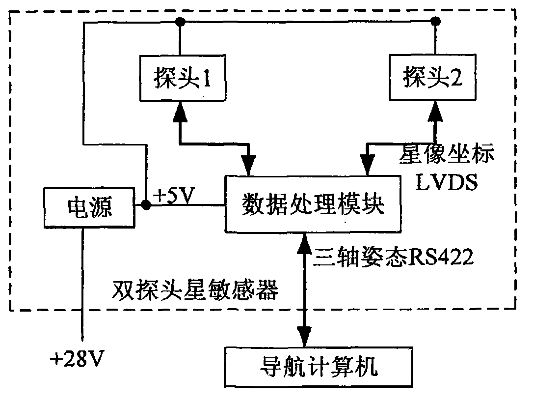
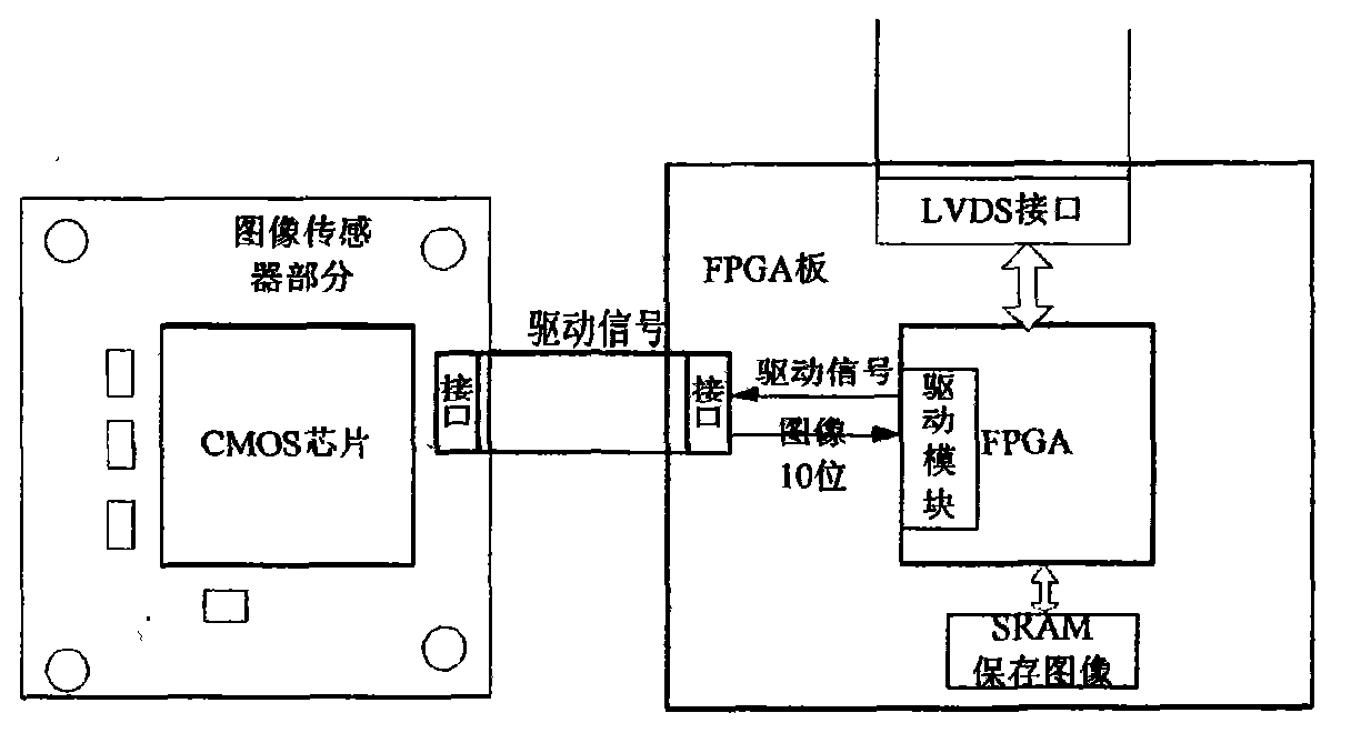
[0053] Example 1: Combining Figure 1-Figure 14 , a dual-probe star sensor of the present invention, which is composed of two imaging probe modules, a CPU data processing module and a power conversion module, the two imaging probe modules are respectively connected to the CPU processing board, the interface adopts LVDS, the two The two imaging probe modules are independent of each other. Considering the problem of transmission time delay, it is not the whole image that the two imaging probe modules transmit to the CPU data processing board, but the star image coordinates in the image. In order to facilitate the CPU data processing board to compare the two Data fusion of two imaging probe modules. In addition to transmitting the star image coordinates in the image to the CPU data processing board, the two imaging probe modules also send the current probe exposure time to the CPU data processing board. The two imaging probe modules are connected to the CPU. In addition to the da...

Embodiment 2

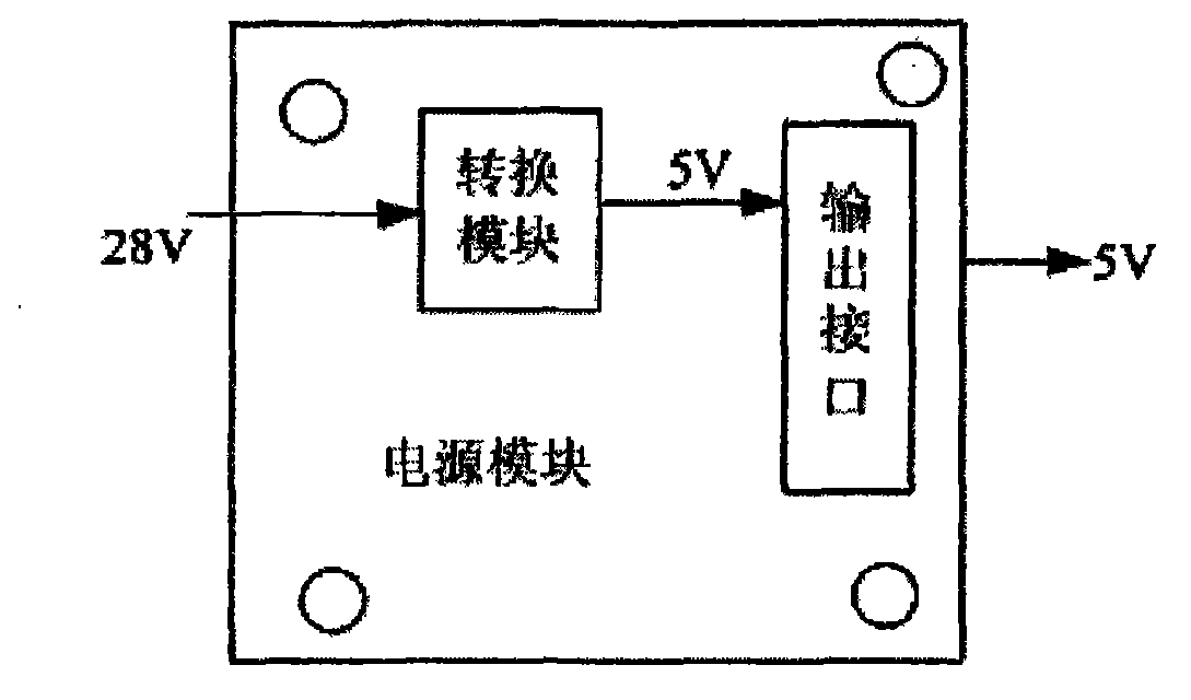
[0084] Example 2: Combining Figure 12, such as error! Reference source not found. It is a power module implementation mode of a dual-probe star sensor, in which the power conversion module that converts the input +28V to +5V mainly uses FMSA-461 and MSA2805S devices, the CMOS imaging device uses CMV4000, and the FPGA device uses EP2C8Q208I8 of ALTERA Company Chip, the configuration file of the EP2C8Q208I8 chip is placed in the EPCS4 device. The SRAM uses IS61LPS204818A. This chip is a 2M×18-bit memory, so two chips are needed, which are the high 18-bit address and the low 18-bit address. The DSP device uses TI The company's TMS320VC33 chip is a 32-bit floating-point device. The program SRAM uses Is611v512616. This chip is a 16-bit memory, so two chips are needed, which are high 16 bits and low 16 bits. RS422 devices use 82C52 chips , FLASH device uses AT49BV162A, the chip is a 16-bit memory, so two chips are needed, which are high 16 bits and low 16 bits, LVDS device uses D...

Embodiment 3

[0085] Example 3: Binding Figure 6-Figure 12 , in order to verify the accuracy of the dual-probe star sensor, and compared it with the accuracy of the single-probe star sensor for field star observation. The experiment was divided into three groups.

[0086] The first group of experimental methods is as follows: turn off the power supply of the imaging probe module (2) of the dual-probe star sensor, at this time, only the imaging probe module (1), CPU data processing module and power supply module work (such as error! Reference source not found .), the imaging probe module (1) is randomly aligned to a certain sky area in the sky, and remains relatively stationary with the earth. The CPU data processing module periodically sends star image coordinate requests to the imaging probe module (1), and the data processing module receives the imaging probe module (1). After the star image coordinate data sent by the module (1), identify these star image coordinates, use the recogniti...


PUM


Abstract

The invention discloses a double-probe star sensor and a method for designing the same. The double-probe star sensor comprises two imaging probe modules, a central processing unit (CPU) data processing module and a power conversion module, wherein the two imaging probe modules are respectively connected with the CPU data processing module, interfaces adopt low voltage differential signaling (LVDS), the two LVDS interfaces are used to periodically time the two imaging probe modules, and the two imaging probe modules respectively and independently keep time within two timing periods. The method for designing the double-probe star sensor comprises: step 1, designing the power conversion module; step 2, designing the probe modules; and step 3, designing the data processing module. The double-probe star sensor is used for overcoming the defects of increased time difference between the two imaging probe modules and poor attitude precision of a rolling axis of the start sensor of the single imaging probe module after the star sensor operates for a long time; and even if a certain imaging probe module fails to work, on the basis of ensuring the attitude precision, the other imaging probe module still can output the attitude, so that the data reliability is improved.

Description

technical field [0001] The invention relates to space technology, specifically a dual-probe star sensor and a design method thereof. Background technique [0002] A star sensor is an optical attitude sensor that senses a star's radiation and measures the satellite's orientation relative to that star. Since the opening angle of the star is very small and the direction of starlight in the inertial coordinate system is known precisely, the measurement accuracy of the star sensor is very high, which is an order of magnitude higher than that of the sun sensor. However, since the starlight is very weak, it is difficult to detect the signal, and its imaging requires the use of a high-sensitivity image sensor, such as a resolution tube or a charge coupled device (CCD, Charge Coupled Device). There are many stars in the sky. On the one hand, it brings the advantages of more target stars to choose from and convenient application, but it also brings difficulties in identifying the det...

Claims


Application Information

Patent Timeline
IPC IPC(8): G01C21/02
Inventor 李葆华王常虹陈希军温奇咏
Owner HARBIN INST OF TECH
Why Eureka
Try Eureka