
Method for determining three-probe star sensor gesture

A determination method and sensor technology, applied in the space field, can solve the problems of the star sensor's reduced star detection ability, the inability to guarantee simultaneous shooting of navigation stars, and the small number of navigation stars.

Active Publication Date: 2012-10-24
HARBIN INST OF TECH
View PDF2 Cites 7 Cited by
  • Summary
  • Abstract
  • Description
  • Claims
  • Application Information

AI Technical Summary

Problems solved by technology

Therefore, it is impossible to reduce the star sensor probe to improve the accuracy of roll angle to the accuracy of yaw angle and pitch angle
[0005] Moreover, the number of navigation stars that can be captured in the star sensor probe of a small probe is relatively small, resulting in a reduction in the star detection capability of the star sensor, which is not conducive to star map recognition and the dynamic performance of the aircraft; Capture enough navigation stars
This will limit the star detection capability of the star sensor and cause a decrease in the accuracy of attitude determination

Method used


Image

  • Method for determining three-probe star sensor gesture
  • Method for determining three-probe star sensor gesture
  • Method for determining three-probe star sensor gesture

Examples


Embodiment 1

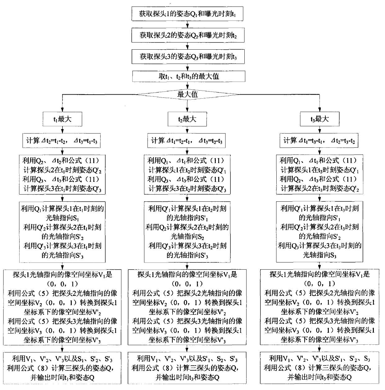
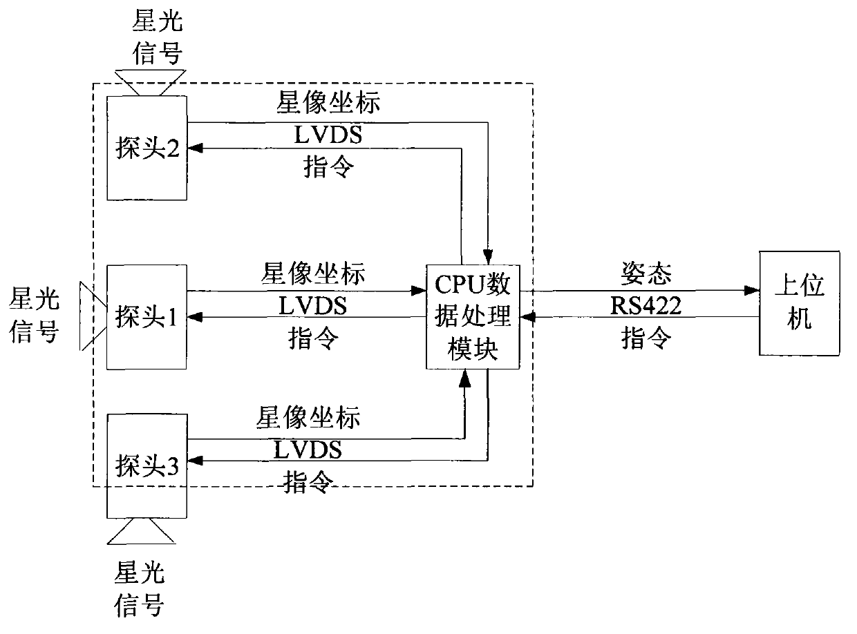
[0047] combine figure 1 , figure 2 , a method for determining the attitude of a three-probe star sensor of the present invention, the steps are as follows:

[0048] The method steps are as follows:

[0049] Step 1: Read separately

[0050] First obtain the attitude Q of the probe 1 and exposure time t 1 ;

[0051] The second obtains the attitude Q of the probe 2 and exposure time t 2 ;

[0052] The third acquisition of the attitude Q of the probe 3 and exposure time t 3 ;

[0053] take t 1 , t 2 and t 3 the maximum value;

[0054] if t 1 max; calculate Δt 2 = t 1 -t 2 , Δt 3 = t 1 -t 3 ;

[0055] Step 2: Use Q 2 , Δt 2 and formula (11)

[0056] q 10 ′ q 11 ′ q ...

Embodiment 2

[0082] combine figure 1 , figure 2 , the attitude determination principle of the three-probe star sensor:

[0083]Three unit vectors X n , Y n ,Z n , and form a mutually orthogonal coordinate system, where: Y n and Z n modulo|Y n |=1 and |Z n |=1, record the new coordinate system F n for

[0084] F n = X n Y n Z n - - - ( 2 )

[0085] The body coordinate system of the spacecraft is F b , the spatial reference coordinate system is F r , and their coordinate bases are

[0086] F b = ...

Embodiment 3

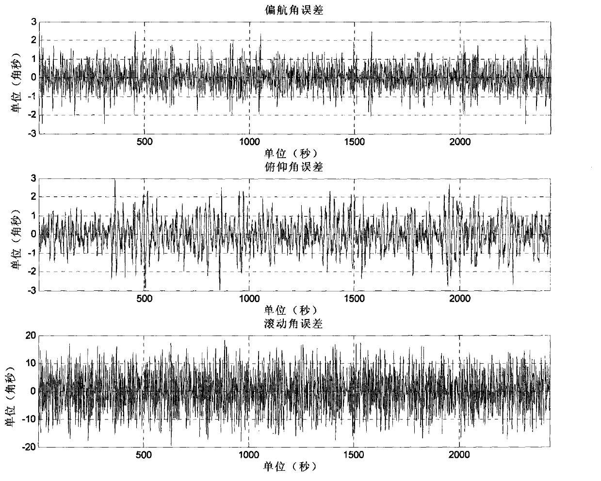
[0113] The experimental method is as follows: figure 2 As shown, put the three-probe star sensor outdoors, place the three-probe star sensor on the turntable of the earth, adjust the turntable so that all three probes can observe enough stars, and the three probes are initially randomly aimed at a certain area of ​​the celestial sphere It is relatively stationary with the earth and rotates with the rotation of the earth for a long time. The three-probe star sensor automatically enters the star tracking mode after all-sky recognition. For the same calculation period, the three-probe star sensor first uses the star map of probe 1 to calculate the attitude, and then uses the star map of the three probes to adopt the method of the present invention. The method calculates attitude, the output adopts the three-axis attitude measurement value of probe 1 and the star map adopting three probes to adopt the method of the present invention to calculate attitude, and outputs these two gr...


PUM


Abstract

The invention discloses a method for determining the three-probe star sensor gesture. A data processing module times two probe modules periodically, so that the defect that time difference between two imaging probe modules is increased after a star sensor is operated for a long time is made up, and the defect of poor gesture precision of a single imaging probe module star sensor rolling shaft is made up. Even if a certain imaging probe module becomes invalid, the other two imaging probes still can output the gesture on the basis of guaranteeing the gesture precision, and the data reliability is improved.

Description

technical field [0001] The invention relates to space technology, specifically a method for determining the attitude of a three-probe star sensor. Background technique [0002] A star sensor is an optical attitude sensor that senses a star's radiation and measures the satellite's orientation relative to that star. Since the opening angle of the star is very small and the direction of starlight in the inertial coordinate system is known precisely, the measurement accuracy of the star sensor is very high, which is an order of magnitude higher than that of the sun sensor. However, since starlight is very weak, signal detection is difficult, and its imaging requires the use of high-sensitivity image sensors, such as image resolution tubes or charge coupled devices (CCD, Charge Coupled Device). There are many stars in the sky. On the one hand, it brings the advantages of more target stars to choose from and convenient application, but it also brings difficulties in identifying t...

Claims


Application Information

Patent Timeline
IPC IPC(8): G01C25/00
Inventor 李葆华陈才敏王常虹陈希军
Owner HARBIN INST OF TECH
Learn More