
High-precision star sensor

A star sensor, high-precision technology, used in astronomical navigation and other directions, can solve problems such as time asynchrony, different crystal oscillators, and inaccurate three-axis attitudes, reducing volume and power consumption, and improving data reliability.

Inactive Publication Date: 2015-04-01
HARBIN INST OF TECH
View PDF7 Cites 0 Cited by
  • Summary
  • Abstract
  • Description
  • Claims
  • Application Information

AI Technical Summary

Problems solved by technology

However, the crystal oscillators of the driving circuits of each probe are different, and there is a phase difference after a long time. Within the time synchronization time when all the probes receive the data processing unit, there is a shortcoming of time asynchronous between the probes. Due to the time asynchrony, use these probes to calculate The three-axis attitude is not accurate enough
The present invention proposes a new multi-sensor drive design method, which is a completely synchronous mode, and the method has high attitude precision in the asynchronous mode, avoiding the use of time-second pulses between the data processing unit and the probe in the traditional asynchronous mode Disadvantages of time synchronization between and data lines

Method used


Image

  • High-precision star sensor
  • High-precision star sensor
  • High-precision star sensor

Examples


Embodiment 1

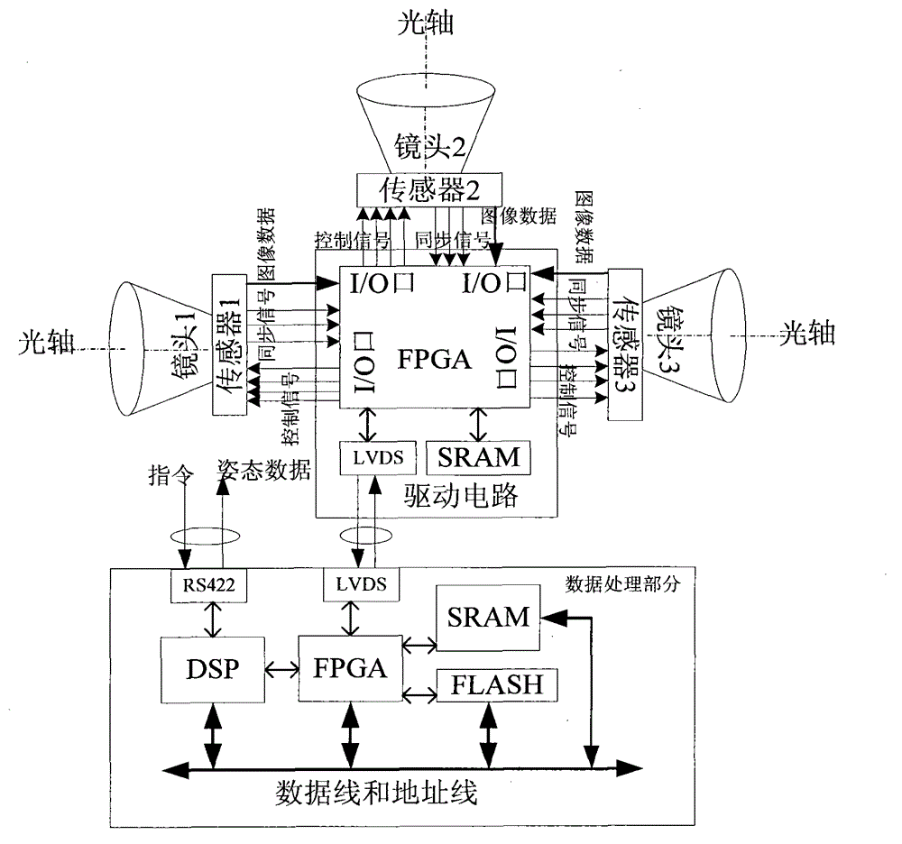
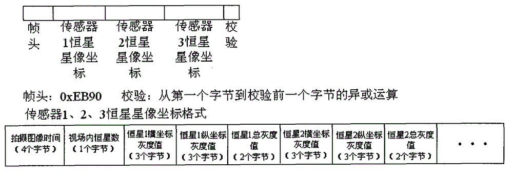
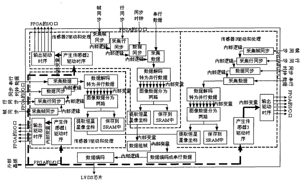
[0035] The design of the present invention is as figure 1 , including three image sensors, each image sensor has an independent lens, and the three image sensors share a driving circuit. Since FPGA has the characteristics of completely parallel operation, this driving circuit only needs one FPGA chip, and the three image sensors The driving signals are all completed by this FPGA chip, which not only greatly reduces the size of the star sensor, but also reduces the power consumption of the star sensor. When the drive circuit receives images from three image sensors, in addition to saving the three images to In SRAM, it is also necessary to extract the stellar image coordinates from the three images. After the stellar image coordinates are extracted from the three images, a packet of data is formed and sent to the data processing part. The data processing part unpacks the data after receiving the data. , respectively identify the star image coordinates of the three image sensors...

Embodiment 2

[0060] Traditionally, to further improve the accuracy of the star sensor, a large area array image sensor is used to design. Although this method can improve the attitude accuracy of the star sensor, its roll angle accuracy is low. The data update rate of the sensor. In order to improve the accuracy of the roll angle of the star sensor, the star sensor is currently designed as multiple probes. The working mode between the probes of the multi-probe star sensor can be synchronous mode or asynchronous mode. The synchronous mode is that multiple probes simultaneously expose the same The star map of time uses the data of all probes and adopts the method of information fusion to improve the accuracy of the star sensor, but in fact, due to the influence of circuit design and process, the time delay is inconsistent, so in actual engineering, all probes cannot be completely the same Take pictures all the time. The asynchronous mode is a time calibration method in which probes are expo...

Embodiment 3

[0063] Take three image sensors, a driving circuit part, and a data processing part as examples below.

[0064] Each image sensor features:

[0065] Field of View: 14°×14°

[0066] Area array: 1024×1024

[0067] Detected magnitude: 6Mv

[0068] Data update rate: 8Hz

[0069] The core FPGA chip of the drive circuit part adopts EP2V8Q208I8, the input crystal oscillator frequency is 40MHz, and the LVDS speed of data transmission is 10Mbps.

[0070] Data processing operating frequency is 50MHz.

[0071] In order to verify whether the accuracy of the high-precision star sensor is synchronized with the star map taken by each image sensor, a comparison is made with the three-field star sensor. The experiment was divided into two groups.

[0072] The first group of experiments is used to test whether there is a phase difference when each image sensor takes a star map. Keep the star sensor relatively stationary with the earth, adjust the orientation of the high-precision star se...


PUM


Abstract

A high-precision star sensor comprises a star image coordinate acquisition unit and a start image coordinate data processing unit. The star image coordinate acquisition unit comprises three image sensors, three analog / digital (A / D) conversion chips, a first field programmable gate array (FPGA) driving unit, a first static random access memory (SRAM) storage unit and a low voltage differential signaling (LVDS) chip, wherein the first FPGA driving unit drives the three image sensors and extracts star image coordinates at the same time. The start image coordinate data processing unit comprises a remote sensing (RS) 422 communication unit, a second FPGA driving unit, a digital signal processor (DSP) control unit, an FLASH storage unit and a second SRAM storage unit. Each image sensor is provided with an independent camera lens, indication directions of every two optical axes of the three camera lenses are perpendicular to each other, the first FPGA driving unit is connected with the second FPGA driving unit through the LVDS chip, and the second FPGA driving unit is connected with the DSP control unit, the FLASH storage unit and the second SRAM storage unit. The high-precision star sensor overcomes the defects that phase differences exist in time among view fields and rolling axes are poor in posture accuracy, reduces the size and power consumption, and improves data reliability.

Description

technical field [0001] The invention relates to a high-precision star sensor. Background technique [0002] A star sensor is an optical attitude sensor that senses a star's radiation and measures the satellite's orientation relative to that star. Since the opening angle of the star is very small, and the direction of the starlight in the inertial coordinate system is precisely known, the measurement accuracy of the star sensor is very high. In order to reduce the influence of external stray light, it is often Add a light shield, and the star sensor further obtains the direction of the starlight vector in the star sensor coordinate system according to the focusing geometric relationship, and then obtains the observation vector of the starlight vector in the carrier body coordinate system from the installation matrix. [0003] In order to further improve the accuracy of the star sensor, a large area array image sensor (such as the 2048×2048 pixel large area array image sensor...

Claims


Application Information

Patent Timeline
Patent Type & Authority Patents(China)
IPC IPC(8): G01C21/02
Inventor 李葆华黄瀚王常虹陈希军
Owner HARBIN INST OF TECH
Learn More