PLC (planar lightwave circuit) splitter

A technology of optical splitter and box body, applied in the direction of fiber mechanical structure, etc., can solve the problems of short service life, easy failure, high replacement frequency, etc., achieve reasonable component distribution, prolong service life, practical and convenient effects

Inactive Publication Date: 2013-02-06
CHANGZHOU LINKET ELECTRONICS TECH
View PDF0 Cites 20 Cited by
  • Summary
  • Abstract
  • Description
  • Claims
  • Application Information

AI Technical Summary

Problems solved by technology

[0003] In order to overcome the disadvantages of existing PLC optical splitters, such as troublesome maintenance, easy failure, high replacement frequency and short service life, the present invention provides a PLC optical splitter

Method used


Image

  • PLC (planar lightwave circuit) splitter

Examples


Embodiment Construction

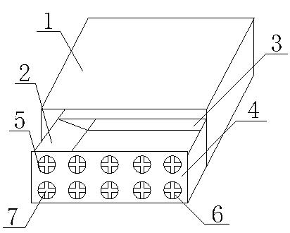
[0011] Such as figure 1 It is a structural schematic diagram of the present invention, a PLC optical splitter, including a housing 1, a box body 2, a partition 3, a panel 4, a hole 5, a sponge 6 and a cross-shaped opening 7, and the housing 1 is slidably connected to the box body 2, A partition 3 is arranged inside the box body 2, and a hole 5 is arranged on the panel 4 of the box body 2, and a sponge 6 is filled in the hole 5, and a cross-shaped opening 7 is arranged on the sponge 6.

[0012] When in use, the shell 1 is slidingly connected to the box body 2, and the inside of the box body 2 is separated by a partition 3, so that the distribution of the optical splitter components is relatively reasonable. There are holes 5 on the front panel 4 of the box body 1, and the sponge 6 is filled in In the hole 5, the sponge 6 has a cross-shaped opening 7, which can prevent dust from entering the box body 2. This kind of PLC optical splitter is simple in structure, practical and con...


PUM


Abstract

The invention relates to the technical field of packaging of photoelectric devices, in particular to a PLC (planar lightwave circuit) splitter which comprises a casing, a box, a partition, a panel and holes. The casing is slidably connected with the box. The partition is disposed in the box. The holes are arranged on the panel of the box and are filled with sponge which is provided with cross apertures. The PLC splitter is simple in structure, practical and convenient. The PLC splitter can be examined and repaired only by drawing out the box due to the convenient drawer structure, and the use of the PLC splitter is greatly facilitated. PLC splitter components can be mounted in the box well, distribution of the components is reasonable, production is facilitated, influence by entering dust is relieved, the service life of the PLC splitter is prolonged, replacement frequency and using cost are lowered, and the PLC is convenient to apply and popularize.

Description

technical field [0001] The invention relates to the technical field of optoelectronic device packaging, in particular to a PLC optical splitter. Background technique [0002] The existing PLC optical splitter uses a sealed structure, so when the optical splitter fails, it is very troublesome to overhaul. It is necessary to unscrew the screw with a screwdriver to carry out the next maintenance work. At the same time, the existing optical splitter The hole on the cover is very large, which makes it easy for dust to enter the chassis, shortening the service life, increasing the frequency of replacement and the cost of use. Contents of the invention [0003] In order to overcome the disadvantages of troublesome maintenance, easy failure, high replacement frequency and short service life of the existing PLC optical splitter, the invention provides a PLC optical splitter. [0004] The technical solution adopted by the present invention to solve the technical problem is: a PLC o...

Claims


Application Information

Patent Timeline
Patent Type & Authority Applications(China)
IPC IPC(8): G02B6/44
Inventor 叶建国
Owner CHANGZHOU LINKET ELECTRONICS TECH
Why Eureka
Try Eureka