Rotary column selector valve

一种旋转阀、圆弧的技术,应用在多通阀、阀装置、仪器等方向,能够解决增大污染、增大使用者、设计复杂等问题

Active Publication Date: 2013-02-06
BIO RAD LAB INC
View PDF5 Cites 24 Cited by
  • Summary
  • Abstract
  • Description
  • Claims
  • Application Information

AI Technical Summary

Problems solved by technology

This complicates the design of the valve and in some cases requires the valve to be turned through 180 degrees, increasing the possibility of user error when the valve is turned too far or not far enough, and when the valve must be turned through When one or more positions are used to achieve the required position, it also increases the possibility of contamination

Method used


Image

  • Rotary column selector valve
  • Rotary column selector valve
  • Rotary column selector valve

Examples


Embodiment Construction

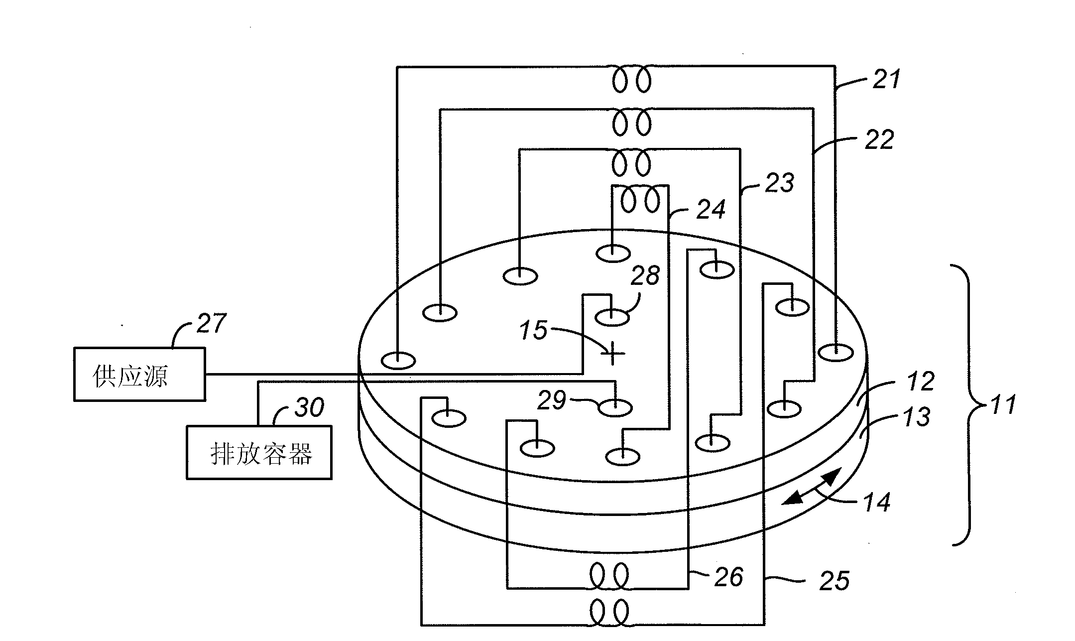
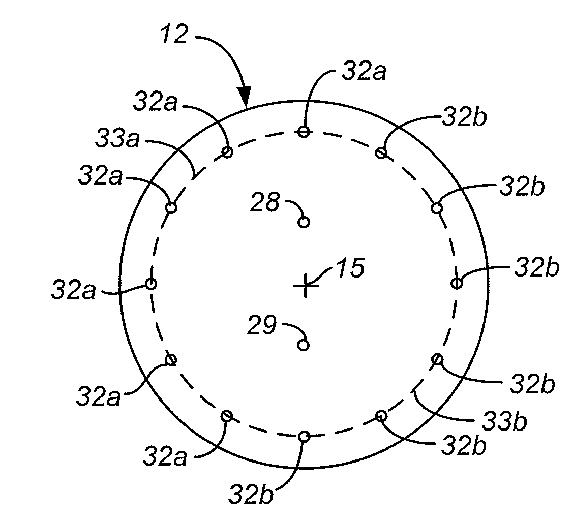
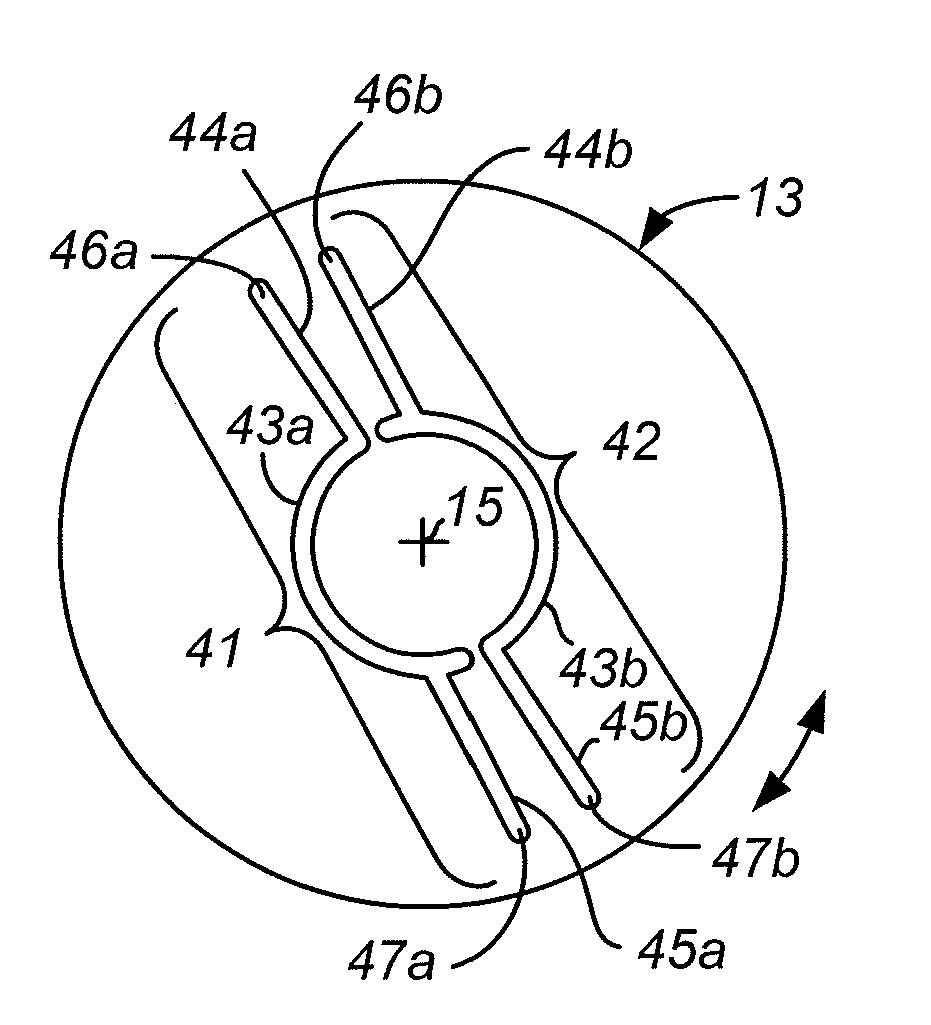
[0013] As noted above, the term "component" is used herein to denote the unit to which the rotary valve supplies fluid or from which it receives fluid. Many such cells are flow-through cells. Examples of such "components" are cylinders, loops, filters and detectors. The term "component port" is used herein to denote a port in a rotary valve that is connected to a component, in many cases, through a connecting tube. Component ports are used to supply fluid to and receive fluid from a component, and typically a component is connected to two component ports, one for supplying fluid to the component and the other for receiving fluid leaving the component.

[0014] The term "valve inlet port" is used herein to denote a port of a rotary valve designated to receive fluid from a fluid supply external to the valve and through which fluid enters the internal chamber of the valve for delivery to the component port. Likewise, the term "valve outlet port" is used herein to denote a port ...


PUM


Abstract

A rotary valve is designed to include a stator with multiple pairs of ports for connection to flow-through components and a rotor with elongated recesses that form flow channels with minimal dead volume and that permit a reversal of flow direction through any component by rotation of the valve through a very small angle.

Description

[0001] Cross-references to related applications [0002] This application claims the benefit of priority to US Provisional Patent Application No. 61 / 346,752, filed May 20, 2010, the contents of which are incorporated herein by reference. Background technique [0003] Rotary valves are used in analytical laboratories and appliances that direct fluid flow to system components such as cylinders, loops, filters, detectors, etc., and for switching between different components and between different fluid sources. Rotary valves can thus be used to select and switch between components for such purposes as sample injection, sample stream selection, fluid diversion, fraction collection, solvent or buffer selection, etc., as well as for different layer Choose between analytical cylinders. A typical rotary valve has a stator and a rotor, with internal passages, usually in the form of slots (elongated depressions), in the surface of the stator or rotor (most often in the rotor), which br...

Claims


Application Information

Patent Timeline
Patent Type & Authority Applications(China)
IPC IPC(8): F16K11/074
CPCF16K11/074G01N30/20G01N2030/202Y10T137/86863Y10T137/0318Y10T137/86533F16K11/072
Inventor G·普莱斯
Owner BIO RAD LAB INC
Why Eureka
Try Eureka