Negative dead volume syringe

a dead volume, negative technology, applied in the field of syringes, can solve the problems of inability to accurately and reliably pump liquid, the system is dead, and the accuracy and reliability of the pumping of liquid is unacceptable, so as to improve the efficiency of forcing, improve the efficiency of pumping, and reduce the loss of fluid

Active Publication Date: 2015-06-16
HAMILTON CO
View PDF6 Cites 25 Cited by
  • Summary
  • Abstract
  • Description
  • Claims
  • Application Information

AI Technical Summary

Benefits of technology

[0015]Accordingly, and in one aspect, an embodiment of the invention ameliorates or overcomes one or more of the shortcomings of the know prior art by providing a negative dead volume syringe that eliminates syringe dead volume and that subtracts or directly displaces dead volume from a valve coupled to the syringe thereby resulting in a syringe pump system that provides faster, more reliable system priming and purging with less fluid loss and that increases the efficiency in forcing air including bubbles out of the syringe and coupled valve during system operation.
[0016]In particular, an embodiment of the invention provides a negative dead volume syringe for repetitively aspirating and dispensing fluids in a fluid handling system, the negative dead volume syringe comprising: an elongated body defining a chamber for retaining fluid and having an open proximal end and a distal end; a syringe tip extending from the distal end and having a syringe tip passageway therethrough in fluid communication with the chamber; an elongated plunger rod extending proximally from a distal end of the plunger rod disposed within the elongated body and through the open proximal end of the elongated body to a proximal end of the plunger rod removeably coupleable to a syringe pump motor to produce bidirectional linear displacement of the plunger rod; and a plunger tip comprising a proximal plunger tip portion coupled to the distal end of the plunger rod, a medial plunger tip portion distally extending from said proximal plunger tip portion and shaped to complement the syringe tip passageway, and a distal plunger tip portion or nubbin distally extending from said medial plunger tip portion and sized to extend beyond the syringe tip and shaped to be complementally received within and substantially or completely fill a valve dead volume defined by a stationary passageway of a rotary valve coupleable to the syringe tip so that the plunger tip ensures completer or substantially complete dispensing of fluid from the chamber while reducing bubble formation and facilitating bubble removal from the chamber, from the syringe tip passageway, and from the valve dead volume upon distal displacement of the plunger rod and the plunger tip coupled thereto.
[0017]Additionally, and in one embodiment, the plunger tip of the negative dead volume syringe is integrally formed as a single device or monolith of material comprising: a cylindrically shaped proximal plunger tip portion coupled to the distal end of the plunger rod and comprising at least one externally circumscribing seal or rib configured to slideably engage the interior surface of the chamber for providing a tight, leak-free seal between the plunger tip and the chamber; a frusto-conically shaped medial plunger tip portion distally extending from said proximal plunger tip portion and shaped to slideably and conformingly engage a frusto-conically shaped void defining the passageway of the syringe tip; and a cylindrically shaped or slightly tapering distal plunger tip portion or nubbin sized to extend beyond the syringe tip and shaped to be complementally received within and substantially fill the valve dead volume defined by the stationary passageway of the rotary valve so that the plunger tip ensures completer or substantially complete dispensing of fluid from the chamber while reducing bubble formation and facilitating bubble removal from the chamber, from the passageway of the syringe tip, and from the valve dead volume upon distal displacement of the elongated plunger rod and the plunger tip coupled thereto.

Problems solved by technology

Although the aim of mounting the syringe vertically is to help remove air from the syringe as air bubbles rise naturally towards the rotary valve during use, there is an inherent problem with the conventional syringe pump system in that the stationary passageway of the rotary valve creates and defines a dead volume in the system where air becomes trapped and unable to exit therefrom.
As a result of the fact that the air is much more easily compressed than the liquid to be pumped, air bubbles in the syringe can cause the performance to be reduced to a level at which accuracy and reliability of pumping of the liquid is unacceptable.
Hence, these additional strokes result in both time and fluid consumption which both can be costly and in short supply.
Another problem that is common in conventional syringe pump systems is the diminishing return or dilution over time during a purging process such as is associated with switching from a first fluid to a second different fluid.
Although fluid mixture is dispensed from the outlet port of the valve, a portion of the fluid mixture remains trapped within the dead volume of the valve defined by the stationary passageway.
Hence, this results in the need for additional strokes for purging the conventional syringe pump system of fluid thereby resulting in both time and fluid consumption which both can be costly and in short supply.
A further problem associated with conventional syringe pump systems is with respect to the out gassing that is linked with running fluids through conventional syringe pump systems.
When the pressure on the fluid is reduced, the bubbles out gas and turn into bubbles that tend to stay in the syringe or dead volume of the valve and stubbornly stick to the sides thereof.
Moreover, an additional dead volume contributing to the problems described above may be found in the tip of the conventional syringe.

Method used


Image

  • Negative dead volume syringe
  • Negative dead volume syringe
  • Negative dead volume syringe

Examples


Embodiment Construction

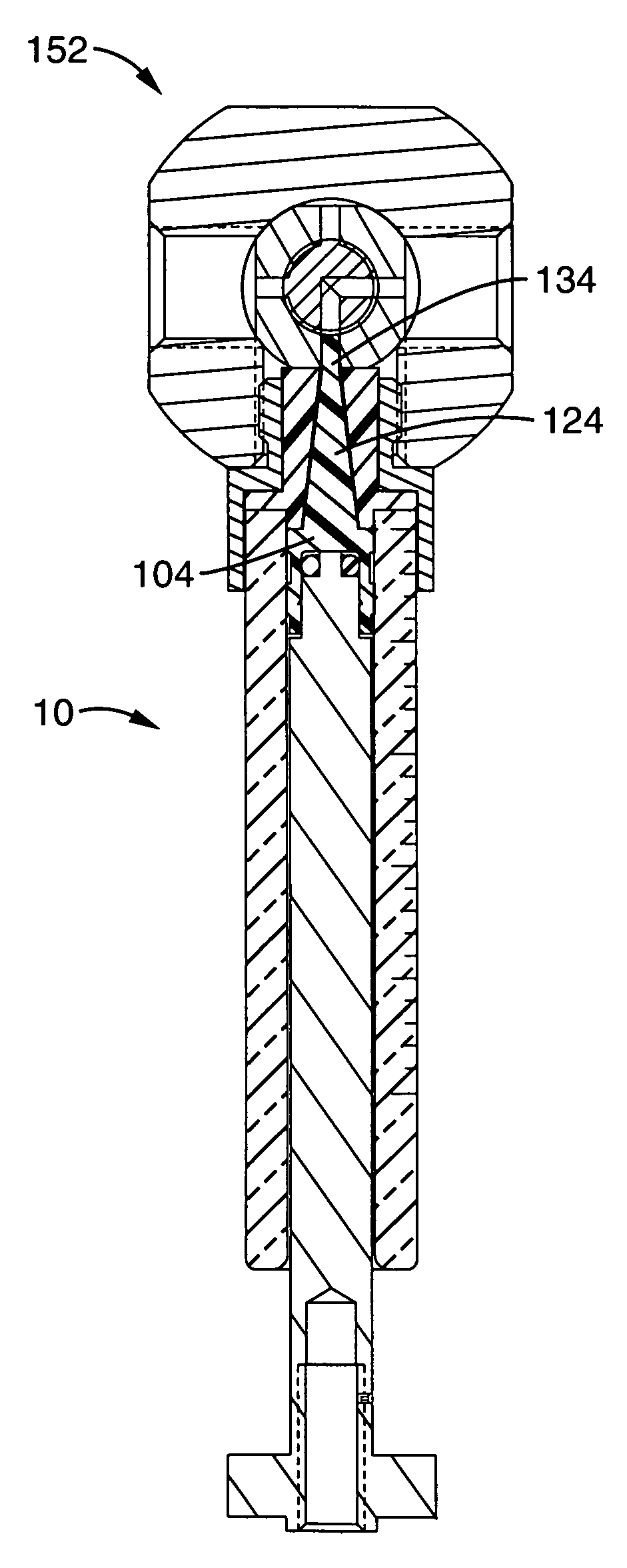
[0041]Considering the drawings, wherein like reference numerals denote like parts throughout the various drawing figures, reference numeral 10 is directed to a negative dead volume syringe according to an embodiment of the present invention.

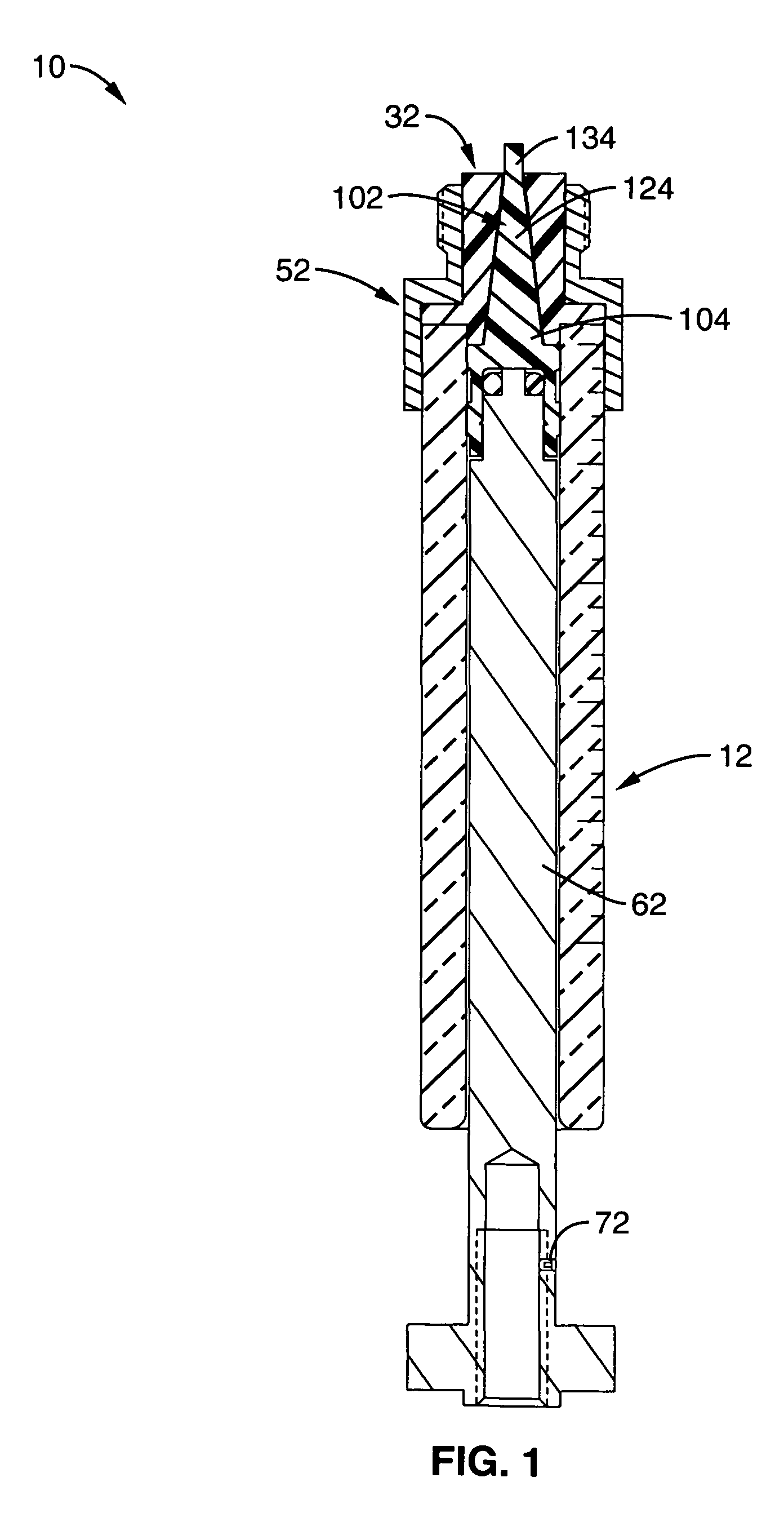
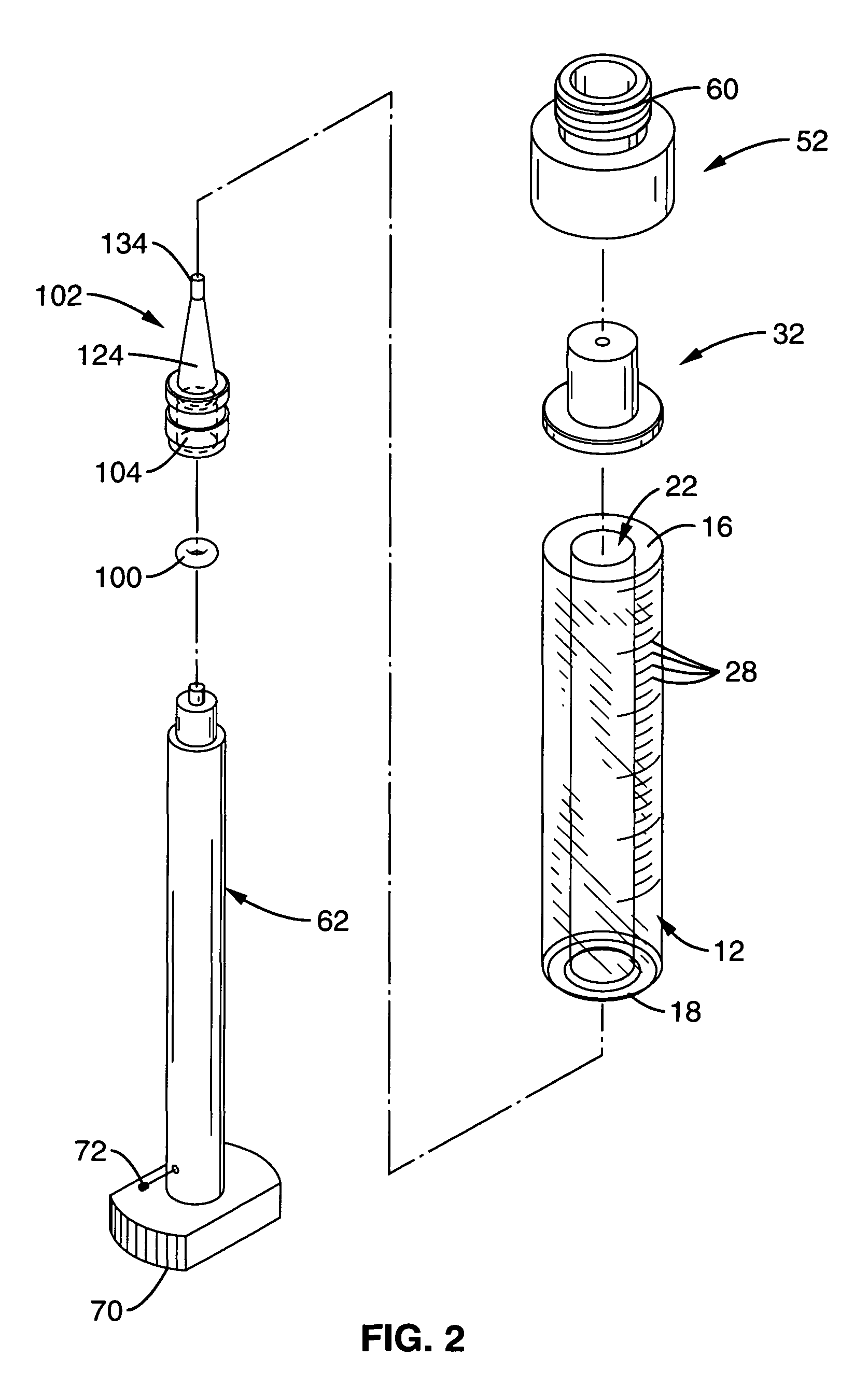
[0042]Referring to FIG. 1, and in one embodiment, the negative dead volume syringe 10 is comprised of a syringe body or barrel 12, a syringe tip 32, a multi-diameter hub 52, a linearly reciprocable plunger 62, and a plunger tip 102.

[0043]Syringe Body or Barrel 12

[0044]Referring now to FIGS. 1 through 4, the syringe body or barrel 12 of the negative dead volume syringe 10 is comprised of a cylindrical sidewall 14 axially-extending between an open distal (front) end 16 and an open proximal (rear) end 18 of the barrel 12. The cylindrical sidewall 14 includes an interior surface 20 that defines an open ended bore or chamber 22 axially extending through the barrel 12 between the open distal end 16 and the open proximal end 18 of the barrel 12.

[0045]Ad...


PUM


Abstract

A negative dead volume syringe comprising a body defining a chamber, a syringe tip disposed at a distal end of the chamber and having a tip passageway therethrough in open communication with the chamber, a rod extending from a first end within the chamber to a second end coupleable to a motor to produce bidirectional motion of the rod, and a plunger tip having a proximal portion coupled to the first end of the rod, a medial portion distally extending from said proximal portion and shaped to complement the tip passageway, and a tip extension distally extending from said medial portion and shaped to be received within a dead volume defined by a passageway of a valve coupleable to the syringe tip wherein the plunger tip ensures evacuation of fluid and air from the chamber, syringe tip, and dead volume of the valve upon distal displacement of the rod.

Description

FIELD OF THE INVENTION[0001]This invention relates generally to syringes and, in particular, to a negative dead volume syringe for use with a syringe pump.BACKGROUND OF THE INVENTION[0002]A conventional syringe pump system for aspirating and dispensing volumes of liquid includes a syringe mounted vertically or horizontally on a syringe pump with a drive means detachable coupled to a plunger emanating from a bottom or rearward end of a chamber of the syringe and a rotary valve detachable coupled to a top or forward end of the syringe in open communication with the chamber.[0003]The rotary valve typically includes a stationary passageway in open communication with both the syringe chamber and a rotatable passageway extending through a rotatable valve member of the rotary valve for providing open communication between the syringe chamber and an inlet port of the valve or an outlet port of the valve as selected by the position of the rotatable valve member. An inlet fluid line typically...

Claims


Application Information

Patent Timeline
Patent Type & Authority Patents(United States)
IPC IPC(8): B01L3/00F04B49/16F04B53/14A61M5/36A61M5/142A61M5/14A61M5/315
CPCF04B49/16A61M5/14216A61M5/36F04B53/14A61M2005/1402A61M2005/31516
Inventor MUNDT, JASON B.EWING, STEPHEN E.
Owner HAMILTON CO
Why Eureka
Try Eureka