
Rotor composite propeller of helicopter

A technology of rotor helicopters and propellers, applied in the field of aircraft, can solve the problems of inability to stall and glide, poor maneuverability, long take-off distance, etc., and achieve the effects of improving flight reliability, reducing overall weight and prolonging life

Inactive Publication Date: 2013-02-13
SOUTH CHINA AGRI UNIV
View PDF10 Cites 6 Cited by
  • Summary
  • Abstract
  • Description
  • Claims
  • Application Information

AI Technical Summary

Problems solved by technology

[0002] Helicopters have the advantages of vertical take-off and landing, hovering in the air, etc., and are widely used. However, when the main propeller stops due to failure, it cannot stall and glide, which is dangerous, and consumes a lot of energy during normal flight.
Rotorcraft has the advantages of gliding, stable flight and low energy consumption, but it has a long take-off distance and poor maneuverability

Method used


Image

  • Rotor composite propeller of helicopter
  • Rotor composite propeller of helicopter
  • Rotor composite propeller of helicopter

Examples


Embodiment 1

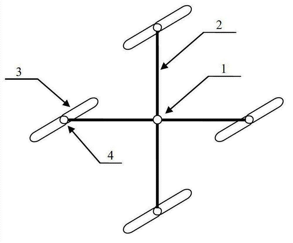
[0020] Such as figure 1 As shown, the composite rotor helicopter propeller includes a main propeller shaft 1, 4 main propeller arms 2, rotor blades 3 and a rotor shaft 4; the main propeller shaft 1 is connected with the helicopter power shaft to provide power for the entire propeller; the 4 main propellers The arms 2 are distributed symmetrically in space. One end of the main propeller arm 2 is fixed on the main propeller shaft 1 , and the other end is installed with a rotor shaft 4 ; the rotor blades 3 are fixed on the rotor shaft 4 .

[0021] When the main propeller shaft 1 with power drives the main propeller arm 2 to rotate, the rotor blades 3 at the ends of the four main propeller arms 2 are driven to rotate by air resistance, and the rotor shaft 4 is an unpowered shaft, so that the rotation plane of the rotor blade 3 is in line with the main propeller The advancing direction of the arm 2 is at a certain elevation angle to generate lift.

[0022] The aircraft is similar ...

Embodiment 2

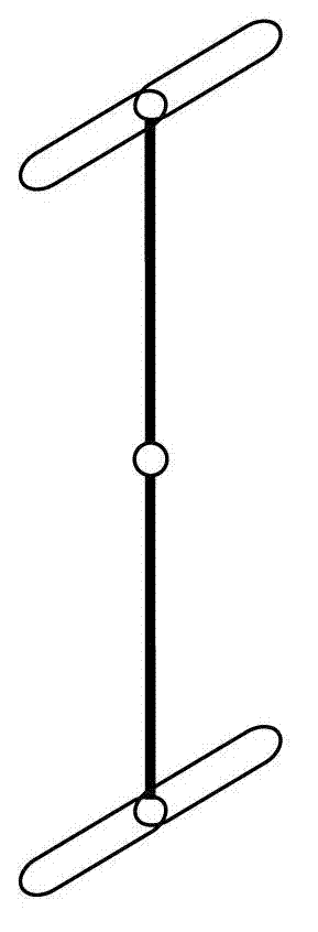
[0025] Such as figure 2 As shown, the composite rotor helicopter propeller includes a main propeller shaft 1, two main propeller arms 2, rotor blades 3 and a rotor shaft 4. The two main propeller arms 2 are symmetrically distributed in space, and the others are the same as in Embodiment 1.

Embodiment 3

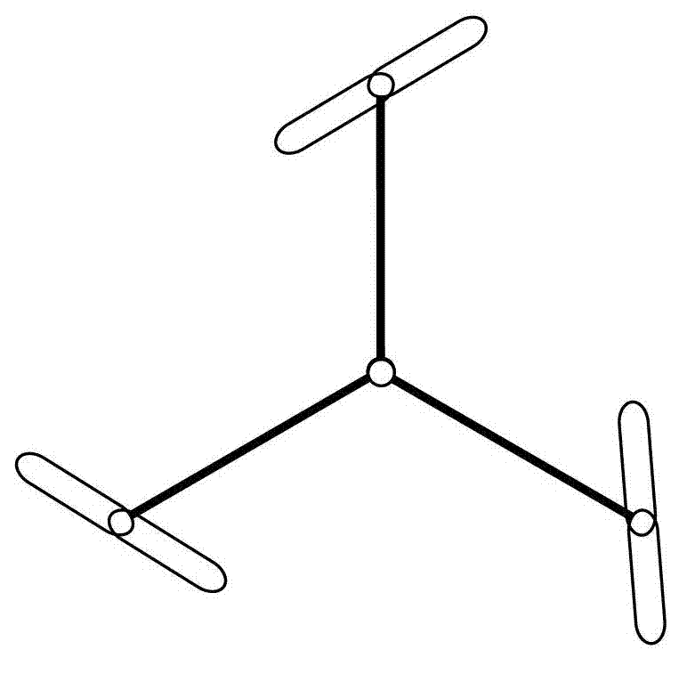
[0027] Such as image 3 As shown, the composite rotor helicopter propeller includes a main propeller shaft 1, three main propeller arms 2, rotor blades 3 and a rotor shaft 4. The three main propeller arms 2 are symmetrically distributed in space, and the others are the same as in Embodiment 1.


PUM


Abstract

The invention discloses a rotor composite propeller of a helicopter. The propeller comprises a main propeller shaft, at least two main propeller arms, rotor blades and a rotor shaft, wherein the main propeller shaft is connected with a power shaft of the helicopter and supplies power for the whole propeller; one ends of the main propeller arms are fixed on the main propeller shaft and the rotor shaft is installed at the other ends of the main propeller arms; and the rotor blades are fixed on the rotor shaft and can rotate freely. The propeller has the advantages of vertical taking off and landing, hovering, good maneuverability, and capability of gliding landing in a rotorcraft mode when the main propeller shuts down due to faults and improving flying stability and security, and the like.

Description

technical field [0001] The invention relates to the field of aircraft, in particular to a compound rotor helicopter propeller. Background technique [0002] Helicopters have the advantages of vertical take-off and landing, hovering in the air, etc., and are widely used. However, when the main propeller stops due to failure, it cannot stall and glide, which is dangerous, and consumes a lot of energy during normal flight. The gyroplane has the advantages of gliding, stable flight and low energy consumption, but it has a long take-off distance and poor maneuverability. Integrating the advantages of the above two aircraft propellers will greatly improve the maneuverability of the aircraft. Contents of the invention [0003] The purpose of the present invention is to overcome the shortcomings in the prior art, and provide a compound rotor helicopter propeller with good maneuverability and simple structure. [0004] The object of the present invention is achieved through the f...

Claims


Application Information

Patent Timeline
Patent Type & Authority Applications(China)
IPC IPC(8): B64C27/08B64C27/14
Inventor 陈润恩闫国琦
Owner SOUTH CHINA AGRI UNIV
Learn More