
Mechanical equipment and anti-deflection mechanism thereof

A mechanical equipment and anti-deflection technology, applied in the field of mechanical equipment, can solve the problems of insufficient lubrication and increase the lubrication cost, and achieve the effect of reducing the lubrication cost and avoiding the insufficient lubrication of the gears.

Active Publication Date: 2013-02-13
ZOOMLION ENVIRONMENTAL IND CO LTD
View PDF6 Cites 1 Cited by
  • Summary
  • Abstract
  • Description
  • Claims
  • Application Information

AI Technical Summary

Problems solved by technology

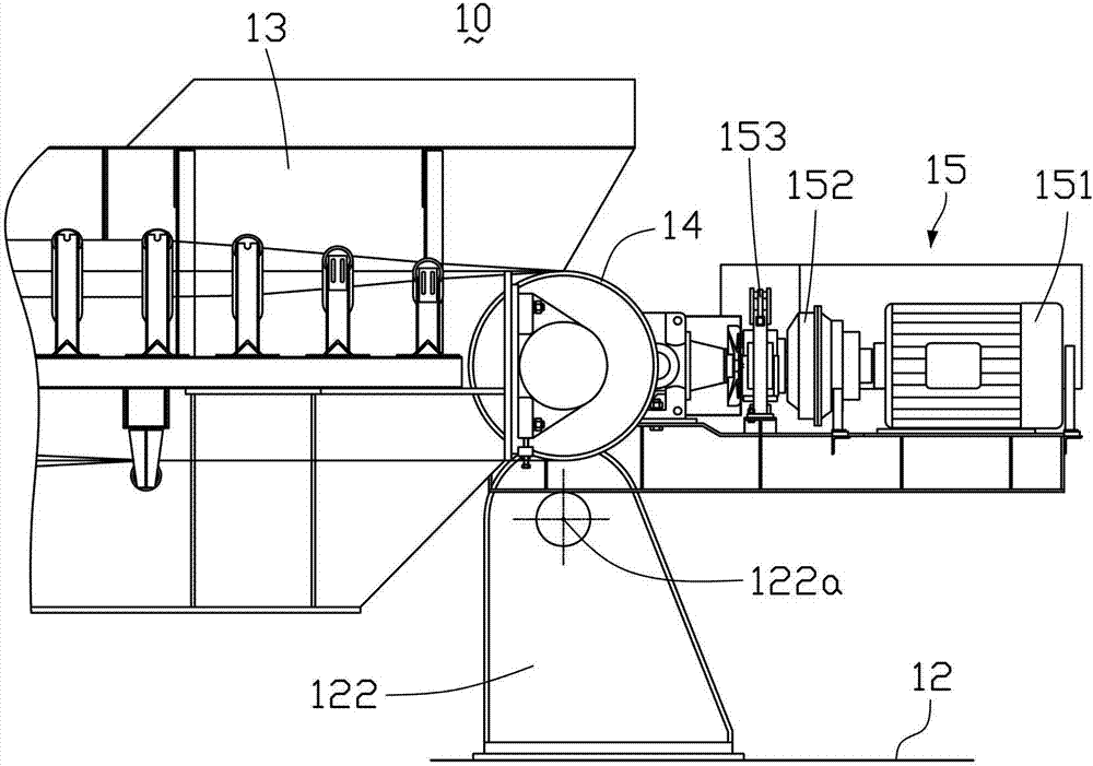
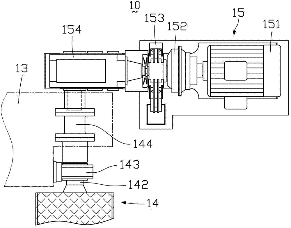
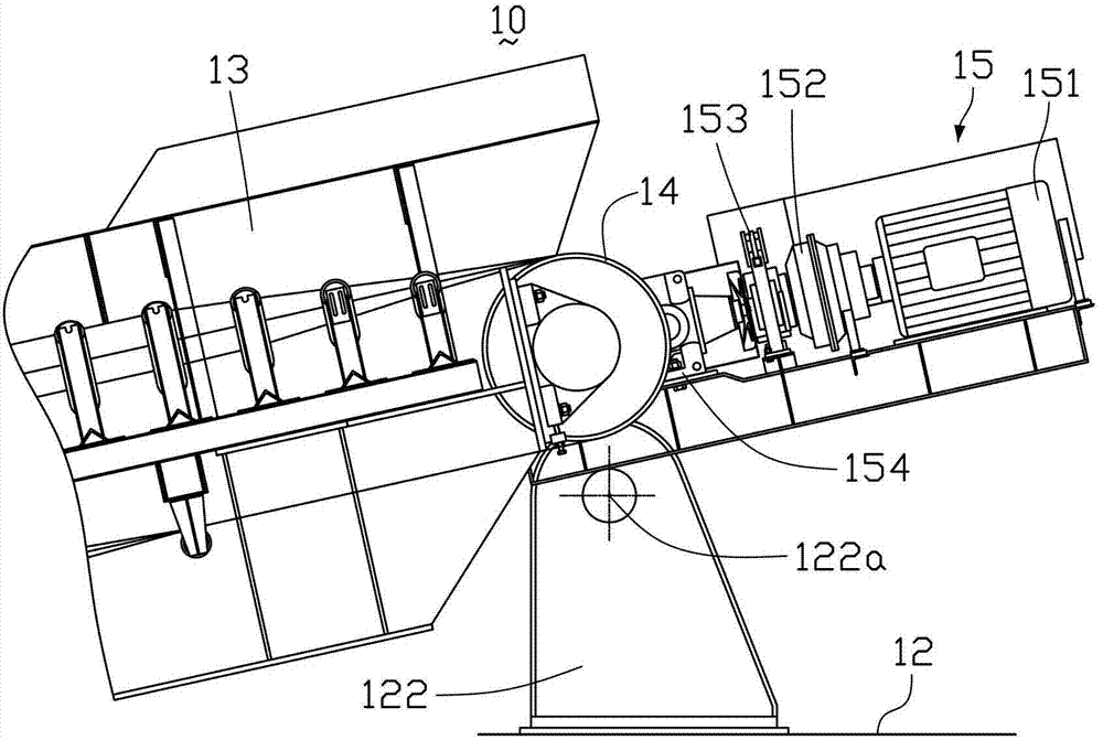
The reducer 154 of the driving device 15 is also deflected accordingly, that is, the reducer 154 is not in a horizontal position, and the gear part of the reducer 154 is separated from the lubricating oil liquid level, resulting in insufficient lubrication, and other auxiliary lubrication measures are required, which increases the lubrication cost

Method used


Image

  • Mechanical equipment and anti-deflection mechanism thereof
  • Mechanical equipment and anti-deflection mechanism thereof
  • Mechanical equipment and anti-deflection mechanism thereof

Examples


Embodiment Construction

[0025] In order to further explain the technical means and effects that the present invention adopts to achieve the intended purpose of the invention, the specific implementation, structure, features and effects of the present invention will be described in detail below in conjunction with the accompanying drawings and preferred embodiments. .

[0026] Figure 5 Shown is a side view partial structural schematic diagram of the mechanical equipment of the embodiment of the present invention, Figure 6 shown as Figure 5 Schematic diagram of the top view partial structure of the mechanical equipment. See Figure 5 and Figure 6 , the mechanical equipment 20 of this embodiment is a bucket wheel machine, but the present invention is not limited thereto.

[0027] The front arm frame 23 can be pitched relative to the fixed platform 22 under the drive of the pitch drive mechanism (not shown in the figure). On the base 222 , the front arm frame 23 can rotate around the hinge axis...


PUM


Abstract

The invention discloses an anti-deflection mechanism which comprises a fixing platform, a pitching member and a drive device, wherein the pitching member is in hinge joint on the fixing platform and can make pitching motion around the hinge-joint axis; and an output end of the drive device is mounted on the pitching member. The anti-deflection mechanism also comprises a connecting rod component; the connecting rod component comprises a connecting rod; the connecting rod has a first end part and a second end part opposite to the first end part; the first end part is in hinge joint on the fixing platform; and the second end part is in hinge joint on the drive device. The invention also provides mechanical equipment. The mechanical equipment and the anti-deflection mechanism disclosed by the invention can prevent the drive device from deflecting substantially along with the pitching member, avoid non-enough gear lubrication of a speed reducer of the drive device, and are favorable for reducing the lubrication cost.

Description

technical field [0001] The invention relates to the field of mechanical equipment, in particular to a mechanical equipment and its anti-deflection mechanism. Background technique [0002] When some mechanical equipment is in use, due to the pitching of the boom, the boom will drive the driving device of the belt conveyor to make a pitching motion at the same time, and the reducer in the driving device will also rotate and deviate from the horizontal position. If the gear of the reducer is lubricated with oil, after the deflection occurs, the gear at the tilted end will inevitably break away from the oil surface, and the lubrication will not be in place. [0003] Take the bucket wheel machine for bulk material transportation as an example, figure 1 Shown is the side view partial structural schematic diagram of existing bucket wheel machine, figure 2 shown as figure 1 The top view of the local structure diagram of the bucket wheel machine. See figure 1 and figure 2 , T...

Claims


Application Information

Patent Timeline
Patent Type & Authority Applications(China)
IPC IPC(8): B65G65/04
Inventor 黄琪明刘阳样肖峰杨平华唐慧永
Owner ZOOMLION ENVIRONMENTAL IND CO LTD
Learn More