Method for operating a fuel system of an internal combustion engine

A fuel system and internal combustion engine technology, applied in the direction of charging systems, fuel injection pumps, fuel injection devices, etc., can solve the problems of high-pressure pump no delivery, high fuel temperature, etc., and achieve the effect of improving durability and improving durability

Active Publication Date: 2013-07-24
ROBERT BOSCH GMBH
View PDF9 Cites 8 Cited by
  • Summary
  • Abstract
  • Description
  • Claims
  • Application Information

AI Technical Summary

Problems solved by technology

[0006] In the above two cases, the high-pressure pump may not work for a long time and have high fuel temperature at the same time

Method used


Image

  • Method for operating a fuel system of an internal combustion engine
  • Method for operating a fuel system of an internal combustion engine
  • Method for operating a fuel system of an internal combustion engine

Examples


Embodiment Construction

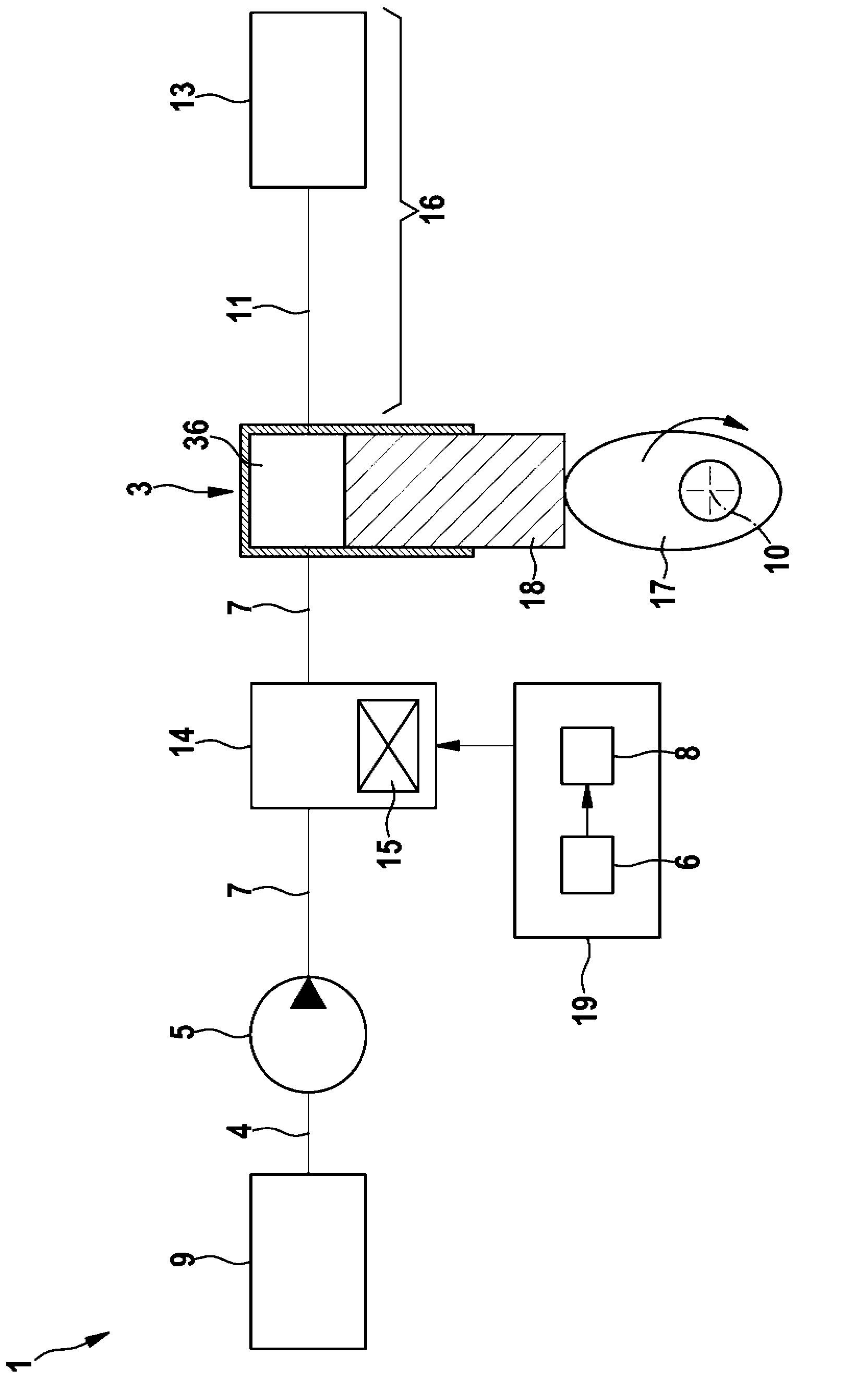
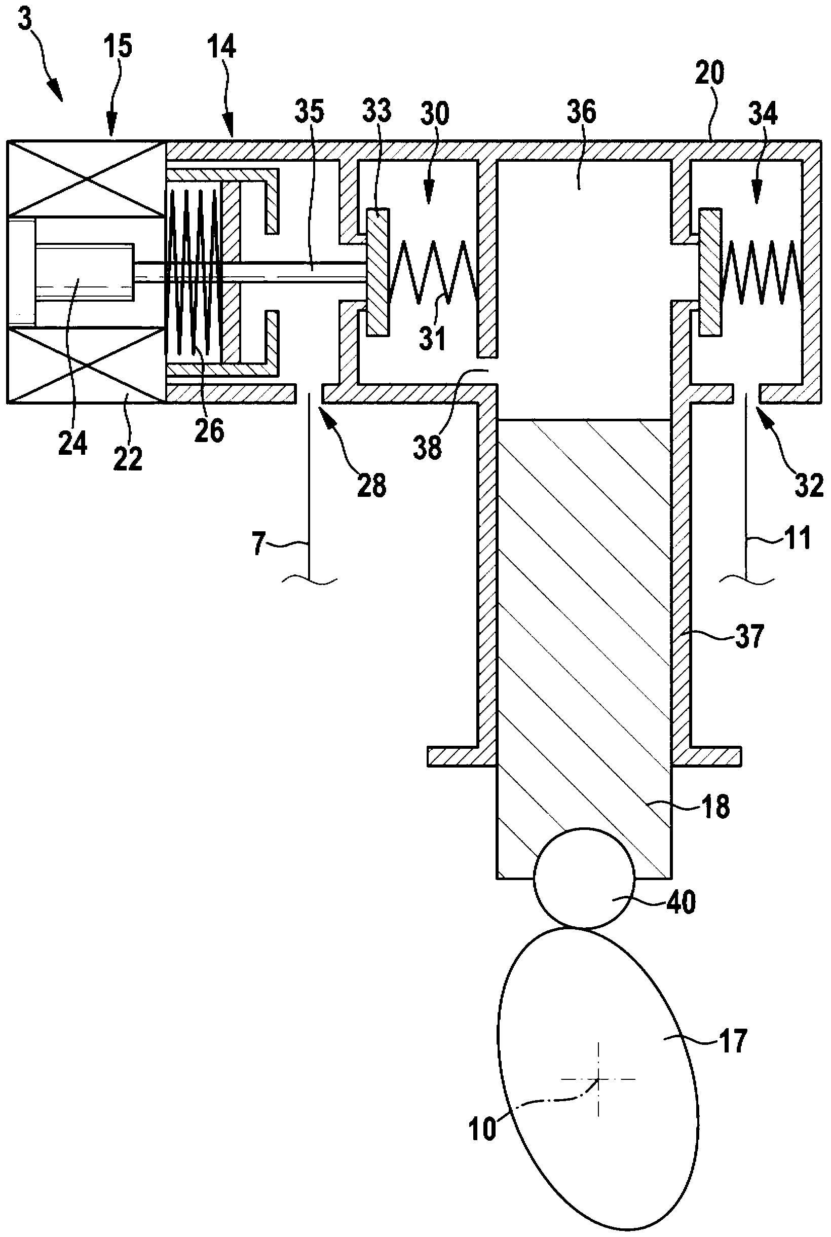
[0034] figure 1 The fuel system 1 of an internal combustion engine is shown in an extremely simplified schematic diagram. A fuel tank 9 is connected to a fuel pump 3 via a suction line 4 , a forward delivery pump 5 and a low-pressure line 7 . A high-pressure accumulator 13 (“common rail”) is connected to the fuel pump 3 via a high-pressure line 11 . The high-pressure line 11 and the high-pressure accumulator 13 together form a pressure region 16 of the fuel system 1 . A solenoid-actuated on-off valve 14—referred to below as valve unit—and a solenoid-actuated device 15—referred to below as solenoid 15—are hydraulically arranged at the low pressure between prefeed pump 5 and fuel pump 3 In the distribution area of ​​the catheter. Electromagnet 15 is controlled by a computer program 8 of a control and / or regulating device 19 using characteristic diagram 6 . Furthermore, the fuel pump 3 includes a cam 17 arranged on the drive shaft 10 which moves a piston 18 vertically in the ...


PUM


Abstract

A method for operating a fuel system (1) of an internal combustion engine is described, in which method, in at least a first operating situation, a fuel pump (3) compresses fuel in a delivery space (36) by means of a corresponding setting of a valve device (14) and feeds said fuel into a pressure region (16), and in at least a second operating situation the fuel pump (3) feeds no fuel into the pressure region (16) by means of a corresponding setting of the valve device (14), wherein in the second operating situation the valve device (14) is at least intermittently actuated in such a way that fuel in the delivery space (36) is compressed but is not fed into the pressure region (16).

Description

technical field [0001] The invention relates to a method according to the preamble of claim 1 as well as a computer program and a control and / or regulating device according to the co-dependent independent claims. Background technique [0002] In modern direct-injection internal combustion engines with demand-regulated fuel delivery, the high-pressure piston pump (HDP) required for this purpose occasionally operates temporarily without fuel delivery, depending on the operating state of the motor vehicle. In conventional systems, this takes place primarily in the thrust-off phase, in which the internal combustion engine does not require fuel and therefore also does not have to deliver fuel. The high pressure pump survives this stage without damage. [0003] A possible damage mechanism for a piston pump used as a high-pressure pump can be described as follows: If a quantity control valve, which is usually connected upstream of the high-pressure pump and controls the quantity o...

Claims


Application Information

Patent Timeline
Patent Type & Authority Applications(China)
IPC IPC(8): F02M59/36F02D41/38
CPCF02M59/366F02D41/3845F02M59/368F02D41/38F02M59/36
Inventor J·金佩尔
Owner ROBERT BOSCH GMBH
Why Eureka
Try Eureka