Evaluation method of 10kV three-core cable conductor temperature

A three-core cable and conductor temperature technology, applied to the direction of the thermometer that gives the difference, can solve the problems of large errors, harsh calculation conditions, and insufficient universality, and achieve simplified calculations, wide applicability, and guaranteed calculation accuracy Effect

Inactive Publication Date: 2013-02-13
GUANGZHOU POWER SUPPLY CO LTD
3 Cites 19 Cited by

AI-Extracted Technical Summary

Problems solved by technology

[0004] The above method has the following defects: 1. The surface of the earth is an isothermal surface; 2. The surface of the cable is an isothermal surface; 3. The principle of superposition is applicable; 4. The specified calculation conditions are very hars...

Abstract

The invention discloses an evaluation method of 10kV three-core cable conductor temperature, wherein the conductor temperature is calculated based on the measured cable skin temperature, and the influence of the complicated change of the external environment temperature and environment thermal resistance on the 10kV three-core cable under different laying conditions and different operation environment conditions is avoided, thus the evaluation result is more accurate, and the application range is wider. Moreover, the evaluation method also performs equivalent and simplification treatment in calculation: neglecting the thermal resistance of a conductor shielding layer, considering the conductor and the conductor shielding layer as one layer, and deeming that the temperature of the conductor shielding layer is equal to the temperature on the outer surface of the conductor; considering the insulation shielding in an insulating layer and deeming that the thermal resistance coefficients of the two are equal; and neglecting the loss and thermal resistance of the 10kV three-core cable metal shielding layer. Thus, the method simplifies the operation while guaranteeing the calculation accuracy.

Application Domain

Thermometers using value differences

Technology Topic

Skin temperatureEngineering +3

Image

  • Evaluation method of 10kV three-core cable conductor temperature
  • Evaluation method of 10kV three-core cable conductor temperature
  • Evaluation method of 10kV three-core cable conductor temperature

Examples

  • Experimental program(1)

Example Embodiment

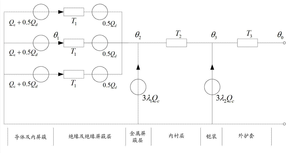
[0023] At present, there are basically two methods to determine the current carrying capacity of a 10kV three-core cable: one is to use the IEC60287 standard, under the conditions of 100% load and typical laying methods, part of the experience value is used to calculate the steady-state current carrying capacity; the other is Carry out the current-carrying capacity experiment under the condition of the same cable load current for laying multiple rows of pipes, and determine the current-carrying capacity of the cable group during actual operation through the experiment. The present invention proposes a new idea in calculating the steady-state conductor temperature of a 10kV three-core cable and determining the current carrying capacity: eliminating the need for the traditional ambient temperature measurement when calculating the current carrying capacity and not considering the changeable environmental thermal resistance, and each in the cable group It can also be calculated under different load currents of cables. The following describes the present invention in detail from the heat production and heat transfer process of a 10kV three-core cable.
[0024] 1. Analyze the heat generation and heat transfer of the single-phase unit length conductor, insulation and insulating shielding layer. The process is: since the thermal conductivity of copper conductor far exceeds that of the insulating layer, the thermal resistance of the conductor can be ignored and only taken into account Conductor loss Q caused by conductor thermal effect c , Perform a π-type equivalent distribution on the dielectric loss and thermal resistance of the insulation and insulation shielding layer, and the thermal resistance is T 1 , The dielectric loss distribution on both sides of the thermal resistance is 0.5Q d.
[0025] 2. Due to the structure of the 10kV three-core cable figure 2 As shown, according to the corresponding properties of the heat circuit and the circuit, the heat flow sources of the three unit-length conductors, insulation and insulation shielding layer are connected in parallel with the thermal resistance.
[0026] 3. Since the thickness of the metal shielding layer is very small compared to the insulating layer, and the thermal resistance and resistance of the copper metal shield are extremely small, the thermal resistance of the three metal shielding layers and their total loss 3λ can be ignored 1 Q c.
[0027] 4. Due to the irregular structure and uneven distribution of the lining layer, the thermal resistance of the lining layer T 2 The calculation is complicated. The present invention relates to the thermal resistance of the inner lining T 2 The calculation is based on the graphical method in IEC60287.
[0028] 5. According to the law of thermodynamics, with the tape in the 10kV three-core cable as the boundary, the total loss of the three internal conductors, insulation and insulation shielding layer, and metal shielding layer needs to be dissipated by the outer sheath layer through the armor. Add the loss 3λ in the armor tape 2 Q c , All heat passes through the outer sheath T 3 After that, it will eventually dissipate heat to the external environment through the cable skin.
[0029] After the above heat production and heat transfer process analysis, the heat circuit diagram is as follows figure 1 As shown, (Note: Although the thermal resistance and loss of the metal shielding layer are ignored, they are still shown in the heat circuit diagram)
[0030] The method for evaluating the conductor temperature of a 10kV three-core cable of the present invention includes the following steps:
[0031] Step S101, monitoring the single-phase conductor current I and the outer sheath skin temperature θ of the 10kV three-core cable 0;
[0032] Step S102: Calculate the temperature difference between the conductor temperature of the 10kV three-core cable and the outer sheath skin temperature, and the calculation formula for the temperature difference is as follows:
[0033] Δθ=(Q c +0.5Q d )T 1 +3(Q c +Q d )·T 2 +3[(1+λ 2 )Q c +Q d ]·T 3
[0034] In the above formula, Δθ represents the temperature difference, T 1 , T 2 , T 3 , Q c , Q d And λ 2 Respectively represent the thermal resistance of the insulation layer, the thermal resistance of the inner lining layer, the thermal resistance of the outer sheath, the conductor loss, the loss of the insulation layer and the loss coefficient of the armor tape of a 10kV three-core cable;
[0035] Step S103, according to the temperature difference Δθ and the outer sheath skin temperature θ 0 ,Calculate the conductor temperature θ 1 :
[0036] θ 1 =Δθ+θ 0
[0037] As described in step S101, this evaluation method requires the monitoring data of the single-phase conductor current size of the 10kV three-core cable and the monitoring data of the outer sheath skin temperature. The current size of a single-phase conductor can be measured by a current transformer, and the skin temperature can be obtained by a thermocouple, a thermometer, or an optical fiber temperature measurement system.
[0038] This evaluation method is suitable for non-turnkey and steady-state 10kV three-core cables. Determine whether the temperature field of the 10kV three-core cable reaches a steady state by monitoring the cable skin temperature data. When the skin temperature data measured by the temperature monitoring equipment changes less than 0.5 ℃ within 5 minutes, the cable temperature field can be considered A steady state is reached.
[0039] According to physical parameters such as the thermal resistance coefficient of each layer of material, the thermal resistance T1 of the insulation and the insulation shielding layer of the 10kV three-core cable mentioned in step S102 is obtained by the following formula; the thermal resistance of the inner lining layer T2 and the thermal resistance of the outer sheath layer T3; Conductor loss Qc, insulation loss Qd, armor tape loss coefficient λ2.
[0040] (1) Thermal resistance T1 of insulating layer:
[0041] At present, most of the 10kV three-core cables in actual operation are metal tape shielded. According to the IEC60287 standard, this type of cable needs to be considered as an insulated cable with d1/d=0.5 (d is the insulation thickness between conductors, d1 is the conductor and metal shield The insulation thickness between the layers), and then the thermal conductivity effect of the metal shielding layer needs to be multiplied by the shielding factor K.
[0042] T 1 = K ρ T 2 π G - - - ( 1 )
[0043] In formula 1: ρ T Is the thermal resistance coefficient of the insulating material, K·m/W; K is the shielding factor; G is the geometric factor.
[0044] Note: The shielding factor K and geometric factor G need to be solved by referring to the graphic method in the IEC60287 standard.
[0045] (2) Thermal resistance of lining layer T 2 :
[0046] T 2 = ρ T 2 π G 0 - - - ( 2 )
[0047] In formula 2: G 0 It is the geometric factor of the inner liner, and the specific calculation refers to the graphic method of the inner liner thermal resistance in the IEC60287 standard.
[0048] (3) Thermal resistance of outer sheath layer T 3 :
[0049] T 3 = ρ T 2 π ln ( 1 + 2 d 3 D a ) - - - ( 3 )
[0050] In formula 3: d 3 Is the thickness of the outer sheath, mm; D a Is the outer diameter of the armor, mm.
[0051] (4) Conductor loss Q c :
[0052] Q c = I 2 R (4)
[0053] In formula 4: I is the single-phase conductor load current, A; R is the AC resistance per unit length of the conductor at 90°C, Ω/m.
[0054] The AC resistance of the conductor also needs to consider the skin effect and proximity effect, the relationship is as follows:
[0055] R=R Z (1+Y S +Y P ) (5)
[0056] In formula 5: Y S Is the skin effect factor; Y P Is the proximity effect factor; R Z It is the DC resistance per unit length of the conductor at 90℃, Ω/m.
[0057] Conductor DC resistance R at 90℃ Z :
[0058] R Z =R 0 [1+a 20 (θ-20)] (Equation 6)
[0059] In formula 6: R 0 DC resistance of conductor at 20℃, Ω/m; a 20 Is the temperature coefficient of cross-linked polyethylene at 20°C; θ is the temperature resistance of cross-linked polyethylene at 90°C, (R 0 , A 20 Can be found through GB/T3956-1997).
[0060] Skin effect factor Y S :
[0061] Y S = X S 4 192 + 0.85 X S 4 - - - ( 7 )
[0062] X S 2 = 8 πf R Z X 10 - 7 k S - - - ( 8 )
[0063] In the above formula: f is the power frequency, H Z; For round stranded wire or compressed round stranded wire, the empirical value of ks value is 1.
[0064] Proximity effect factor Y P :
[0065] Y P = x p 4 192 + 0.8 x p 4 ( d c s ) 2 X [ 0.312 ( d c s ) 2 + 1.18 x p 4 192 + 0.8 x p 4 + 0.27 ] - - - ( 9 )
[0066] x p 2 = 8 πf R Z × 10 - 7 k p - - - ( 10 )
[0067] In the above formula: d c Is the conductor diameter, mm; s is the distance between the conductor axes, mm; for round stranded wire or compressed round stranded wire, its k p The experience value of is 0.8.
[0068] (5) Insulation layer loss Q d :
[0069] Q d = ω · c · U 0 2 · tgδ - - - ( 11 )
[0070] In formula 11: ω=2πf; U 0 Is the phase voltage, V; tgδ is the insulation loss factor under the power system and operating temperature; C is the cable capacitance per unit length, F/m.
[0071] Cable capacitance per unit length:
[0072] c = ϵ 18 ln ( D i d c ) X 10 - 9 - - - ( 12 )
[0073] In formula 12: ε is the dielectric constant of the insulating material, and the value of 10kV cross-linked polyethylene is usually 2.5; D i Is the diameter of the insulating layer, mm; d c Is the conductor diameter, mm.
[0074] (6) Loss coefficient of armor tape λ 2 :
[0075] Armour loss is the sum of hysteresis loss and eddy current loss:
[0076] λ 2 =λ′ 2 +λ″ 2 (13)
[0077] Hysteresis loss:
[0078] λ 2 ′ = S 2 K 2 × 10 - 7 Rd A δ - - - ( 14 )
[0079] The above formula: S is the distance between the axis of each conductor, mm; the equivalent thickness of δ armor, mm; d A Is the average diameter of the armor, mm; the K coefficient is obtained by the following formula, (μ is the relative permeability of the steel strip, usually 300):
[0080] K = 1 1 + d A μδ - - - ( 15 )
[0081] Eddy current loss:
[0082] λ 2 ′ ′ = 2.25 S 2 K 2 δ X 10 - 8 Rd A - - - ( 16 )
[0083] Calculate the parameters according to the above formula, bring the obtained parameters into the formula of step S102 for calculation, and obtain the steady-state conductor temperature θ at that moment 1.
[0084] Use the obtained steady-state conductor temperature θ 1 On the one hand, it can be determined whether the originally set current carrying capacity is reasonable by judging whether the XLPE (cross-linked polyethylene) long-term withstand temperature of 90°C is exceeded, so as to guide the increase or decrease of the load of the cable. On the other hand, it can serve as an early warning function of overheating of the local conductors of the cable.
[0085] In order to verify the accuracy of the calculation method for the steady-state conductor temperature of the 10kV three-core cable, a confirmatory experiment of the 10kV three-core cable loading current and temperature monitoring was designed. Electrical wiring of experimental equipment such as Figure 4 Shown. The experimental device is mainly composed of 5 parts: reactive power compensation capacitor, voltage regulator, current booster, experimental cable (model: YJV 22 -8.7/10kV-3*240mm 2 ), current transformer and automatic thermometer.
[0086] In order to avoid the longitudinal heat transfer problem of the cable as much as possible, the temperature monitoring point is selected at a distance of 4m from the copper bar of the current booster connection. In the experiment, a thermocouple was used to monitor the cable skin temperature θ 0 And conductor temperature θ 1. The laying of thermocouples such as Figure 5 As shown, the diameter of the drilled thermocouple laying hole is 3.5mm.
[0087] The basic parameters of the experimental cable are shown in Table 1.
[0088] Table 1YJV 22 -8.7/10kV-3*240mm 2 Basic parameters of type three-core cable
[0089]
[0090] The experimental cable flow method is: direct current from 0A to 200A, and direct current from 0A to 400A. The automatic thermometer performs temperature monitoring and data storage throughout the entire process, collecting data every 1 second, judging whether the cable temperature field has reached a steady state by checking the temperature data, and reading the steady-state conductor temperature data and the cable skin temperature data. Finally, compare the measured and calculated values ​​of conductor temperature to verify the accuracy of the above-mentioned steady-state conductor temperature calculation method. The comparison results are shown in the table below.
[0091] Table 2 Comparative analysis of measured and calculated conductor temperature
[0092]
[0093] Several sets of skin temperature and conductor temperature data in the above table are selected from different experiments. It is known from the table that using this evaluation method to calculate the steady-state conductor temperature is more accurate when the loading current is small than when the loading current is large. higher. When the load conductor current is 200A, the error is basically controlled within 1°C, while when the load conductor current is 400A, the error becomes larger, basically within 4°C. Overall, it is in line with engineering applications.
[0094] The invention calculates the steady-state conductor temperature of the cable based on the cable skin temperature, can accurately assess the real-time 10kV three-core cable current carrying capacity, and is improved on the calculation of the IEC standard. The external environment temperature, the environmental thermal resistance, and the conductor and the conductor are eliminated. Shielding is classified as one layer, and insulation and insulation shielding are classified as one layer. The invention provides a reliable basis for whether to replace the three-core cable line of a heavy-duty 10kV distribution network, provides a dispatch basis for the regional dispatch of the distribution network, and provides an emergency warning for cable insulation operation overheating. Therefore, the invention can produce greater economic benefits.
[0095] The above-mentioned calculation of the material layers and thermal resistance parameters based on the structural characteristics of the 10kV three-core cable is only applicable to the 10kV three-core cable, but the steady-state conductor temperature is directly calculated by the skin temperature, thereby ignoring the thermal resistance of the external environment. Other forms of cables.
[0096] The accuracy of the parameter calculation in the IEC standard is recognized, so the parameter calculation in the present invention is based on the IEC standard. However, all ideas of simplification, equivalence and calculation based on skin temperature are creative.
[0097] The above-mentioned embodiments only express several embodiments of the present invention, and the descriptions are more specific and detailed, but they should not be interpreted as limiting the scope of the present invention. It should be pointed out that for those of ordinary skill in the art, without departing from the concept of the present invention, several modifications and improvements can be made, and these all fall within the protection scope of the present invention. Therefore, the protection scope of the present invention should be subject to the appended claims.

PUM

no PUM

Description & Claims & Application Information

We can also present the details of the Description, Claims and Application information to help users get a comprehensive understanding of the technical details of the patent, such as background art, summary of invention, brief description of drawings, description of embodiments, and other original content. On the other hand, users can also determine the specific scope of protection of the technology through the list of claims; as well as understand the changes in the life cycle of the technology with the presentation of the patent timeline. Login to view more.

Similar technology patents

Classification and recommendation of technical efficacy words

  • Wide applicability
  • The assessment results are accurate

Ignition interlock device and method

Owner:INTERCEPTOR IGNITION INTERLOCKS

Safety assessment system for bridge structure based on vehicle load

InactiveCN108225811AThe assessment results are accurateEnsure safe operation of bridgesStructural/machines measurementClosed circuit television systemsCrucial pointMonitor weight
Owner:四川西交慧桥科技有限公司
Why Eureka
Try Eureka