
Relay protection tripping matrix test system

A relay protection and testing system technology, applied in the direction of measuring electricity, measuring devices, measuring electrical variables, etc., can solve the problems of incorrect test results and errors in test results, and achieve rich hardware interfaces, strong device self-checking ability, and functional Extensive effect

Inactive Publication Date: 2013-02-13
DEYANG POWER SUPPLY COMPANY STATE GRID SICHUAN ELECTRIC POWER +1
View PDF6 Cites 19 Cited by
  • Summary
  • Abstract
  • Description
  • Claims
  • Application Information

AI Technical Summary

Problems solved by technology

The main transformer trip matrix inspection device mainly relies on hardware to realize the detection of trip matrix, which is easy to cause errors in test results due to hardware errors, and may even cause incorrect test results

Method used


Image

  • Relay protection tripping matrix test system
  • Relay protection tripping matrix test system

Examples


Embodiment Construction

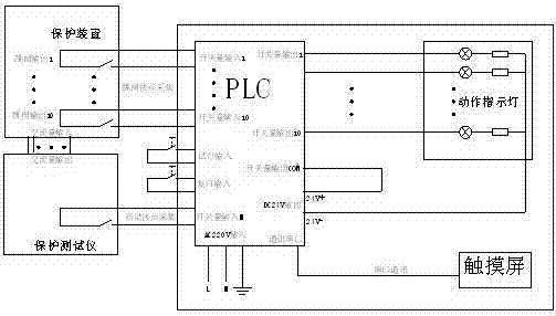
[0024] Such as figure 1 , 2 As shown, the present invention provides a relay protection tripping matrix test system, the AC output end of the relay protection tester is connected to the AC input end of the protection device. The concrete technical scheme of the present invention is described respectively below with hardware device and software method:

[0025] (1) Hardware device:

[0026] The relay protection tripping matrix test system of the present invention includes PLC, action indicator light and man-machine interface, and the hardware connection is very simple, and the basic block diagram is as follows figure 1 shown.

[0027] There are several digital input interfaces and several digital output interfaces on the PLC, among which: there is a working switch interface connected to the fault pulse output terminal of the relay protection tester, and the relay protection tester sends fault pulse signals to the PLC. There are several input interfaces for collecting switch...


PUM


Abstract

The invention provides a relay protection tripping matrix test system which comprises a programmable logic controller (PLC), an action indicator light and a human-computer interface. A relay protection tester sends a fault pulse signal to the PLC; an input interface, a tripping outlet and an output interface are arranged on the PLC, the input interface is used for collecting action conditions of a switch, the tripping outlet is connected with a protection device, the output interface is used for indicating the action conditions of the switch and connected with the action indicator light, the action indicator light corresponds to the tripping outlet, and hardware numbers of the action indicator light and the tripping outlet are same; and a program is stored in the PLC and receives an action signal of a tripping outlet contact of the protection device through the input interface used for collecting the action conditions of the switch, and a lightening signal is sent to the action indicator light through the output interface used for indicating the action conditions of the switch if the tripping outlet contact acts. According to the relay protection tripping matrix test system, action conditions and action time of the outlets can be visually displayed on the indicator light and a touch screen only by simulating various faults, the debugging process is simplified, debugging time is shortened, field work efficiencies are improved, hardware interfaces are plenty, and functional expansibility is high.

Description

technical field [0001] The invention is mainly applied in the field of relay protection of electric power system, and is mainly applied in the exit logic detection of protection devices with many tripping exits, such as transformer protection, bus differential protection and failure protection. Background technique [0002] In the field of power system relay protection, fast and accurate removal of various faults is an important guarantee for the safe and stable operation of the power system. For some protection devices with more complex trip outlets, such as transformer protection, bus differential protection, failure protection, etc., a lot of work needs to be done on the trip outlet circuit during debugging. For such more complicated protection devices at outlets, relay protection debugging The commonly used method in the work is to use a multimeter to test the continuity of the outlet terminal, especially in the test of the trip matrix of the transformer protection outle...

Claims


Application Information

Patent Timeline
IPC IPC(8): G01R31/00
Inventor 蔡华朱林张翠娟唐纲王彬刘兆丰张禹
Owner DEYANG POWER SUPPLY COMPANY STATE GRID SICHUAN ELECTRIC POWER
Learn More