
led aging test system and its test method

A technology of aging test and test system, which is applied in the direction of testing optical performance, single semiconductor device testing, etc., which can solve the test of low efficiency, ignoring temperature characteristics, and not fully considering the forward voltage drop and reverse leakage of LED temperature characteristics. methods and other issues to achieve high efficiency and comprehensive functions

Active Publication Date: 2016-03-23
许伟清
View PDF5 Cites 0 Cited by
  • Summary
  • Abstract
  • Description
  • Claims
  • Application Information

AI Technical Summary

Problems solved by technology

After the test, the LED lights with unqualified parameters are picked out, but after the LEDs selected through this test are officially made into finished lighting products, the LEDs will still have the aforementioned bad phenomena
The reason is that the current aging and testing of LEDs are carried out separately, ignoring the specific temperature characteristics of the LED itself; at different temperatures, its forward voltage drop value and reverse leakage value are different. The current aging method and testing The method does not fully consider the temperature characteristics of the LED and the test method of the LED forward voltage drop and reverse leakage, and the lamp must be taken out several times during the aging process, the parameters are measured, and then put back to continue aging, the efficiency is not high

Method used


Image

  • led aging test system and its test method
  • led aging test system and its test method
  • led aging test system and its test method

Examples


Embodiment Construction

[0035] In order to further illustrate the technical means adopted by the present invention and its effects, the following will be described in detail in conjunction with the embodiments of the present invention and the accompanying drawings, wherein the same reference numerals always represent the same components.

[0036] The explanation of some words used in the present invention is firstly described below, constant current aging: LED is lighted and aged with a fixed forward current; Reverse impact aging: LEDs are aged alternately with forward pulse current and reverse pulse voltage.

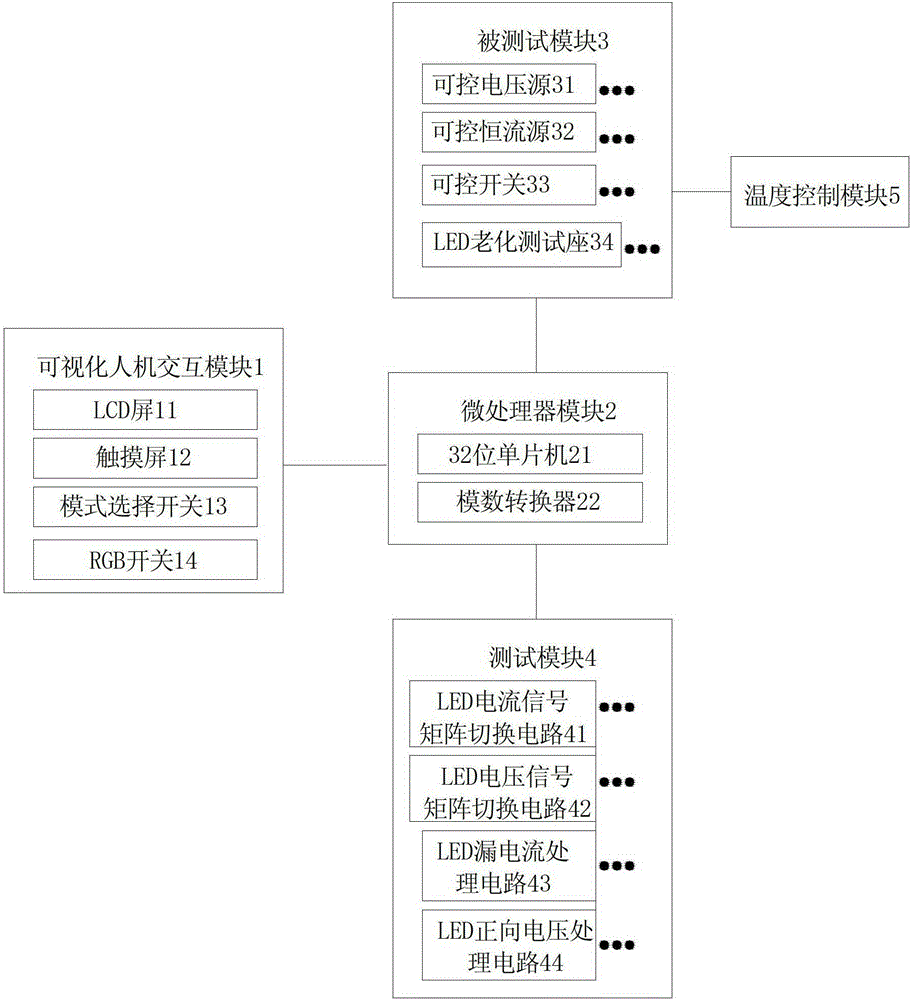
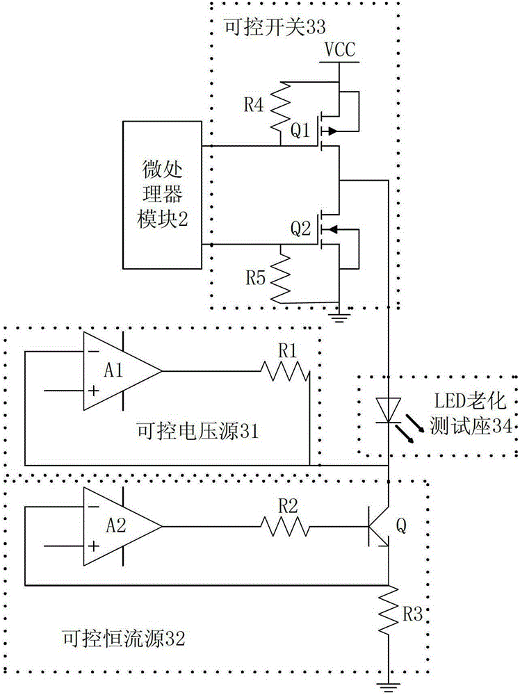
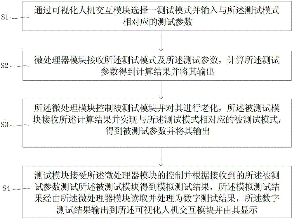
[0037] Such as figure 1 As shown, the LED aging test system can test multiple LEDs at the same time. The test system includes: a visual human-computer interaction module 1, a microprocessor module 2, a tested module 3 and a test module 4; 1 Select a test mode, the test mode is displayed on the visual human-computer interaction module 1, according to the test mode displayed on the visual human...


PUM


Abstract

The invention discloses a light-emitting diode (LED) ageing test system which comprises a visual man-machine interaction module, a microprocessor module, a tested module and a testing module. The visual man-machine interaction module is used for selecting a testing mode, inputting testing parameters corresponding to the testing mode and displaying the testing mode and / or the testing parameters; the microprocessor module is used for receiving the testing mode and the corresponding testing parameters, calculating the testing parameters to obtain calculating results and outputting the results; the tested module is used for receiving the calculating results, achieving a tested mode corresponding to the testing mode to obtain the tested parameters and outputting the tested parameters; and the testing module is used for receiving control of the microprocessor module and testing the tested module according to the received tested parameters to obtain simulation testing results. The simulation testing results are read by the microprocessor module and then processed into data testing results, and then the simulation testing results are displayed on the visual man-machine interaction module. The LED ageing test system can test a plurality of LEDs simultaneously in on-line mode, and is full in function and high in efficiency. The invention further discloses an LED ageing testing method.

Description

technical field [0001] The invention relates to the technical field of LED photoelectric testing, and more specifically relates to an LED aging testing system and a testing method thereof. Background technique [0002] LED has low power and long life, especially in terms of energy saving. Coinciding with the current energy shortage, the development of LED has received strong support from the state, and it has developed very fast in recent years. LEDs are widely used in lighting, including commercial, family, automotive lighting and other fields. [0003] Generally, in theory, the service life of LED can reach 100,000 hours. In the past few years, the LED products we have come into contact with have a very short service life, including street lamps, desk lamps, light pipes, etc. Many LED lamps are lit for a short time After that, the phenomenon of dimming brightness, uneven brightness, color change, or even no light will appear. There are many reasons for this, such as the...

Claims


Application Information

Patent Timeline
Patent Type & Authority Patents(China)
IPC IPC(8): G01R31/26G01M11/02
Inventor 黄永贤
Owner 许伟清
Learn More