
Quality control conveying line

A conveyor line and rear conveyor belt technology, applied in the field of quality inspection conveyor lines, can solve problems such as low work efficiency

Inactive Publication Date: 2018-07-13
黄雪位
View PDF6 Cites 1 Cited by
  • Summary
  • Abstract
  • Description
  • Claims
  • Application Information

AI Technical Summary

Problems solved by technology

However, due to the need for manual inspection and manual selection of defective workpieces, the problem in the above operation process is that the work efficiency is low

Method used


Image

  • Quality control conveying line
  • Quality control conveying line
  • Quality control conveying line

Examples


Embodiment Construction

[0039] The present invention will be described in further detail below in conjunction with the accompanying drawings.

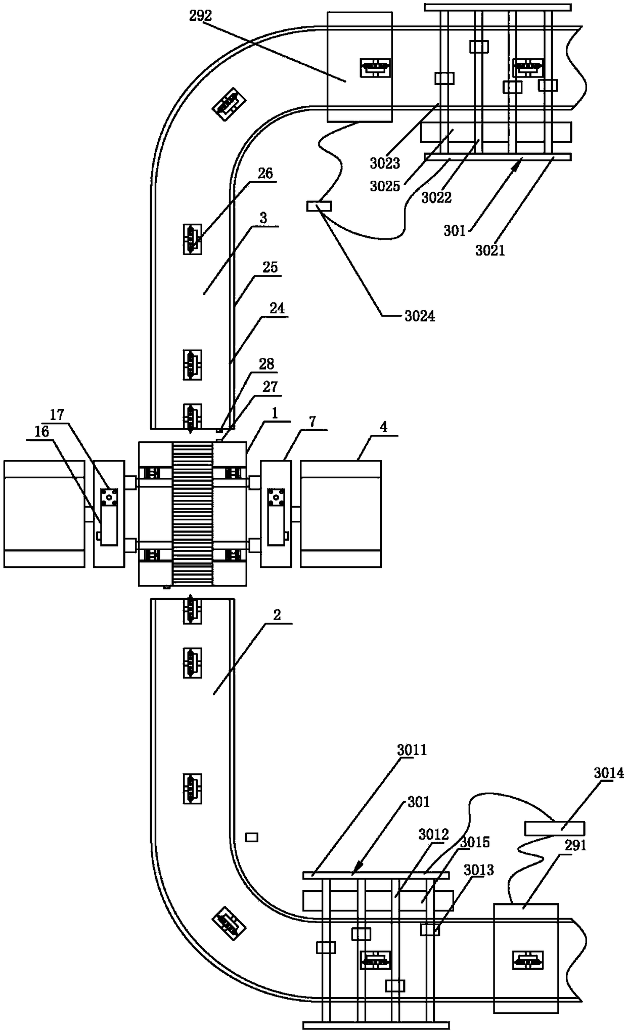
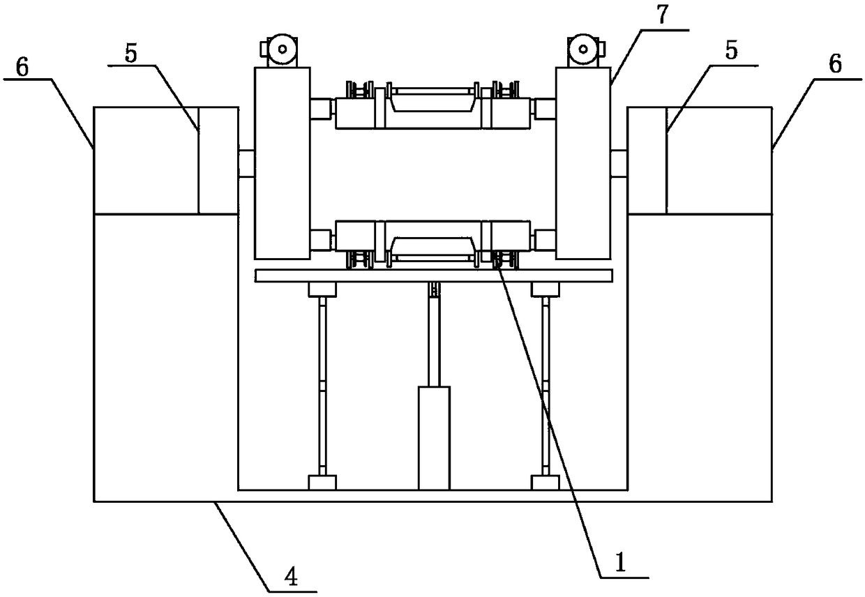
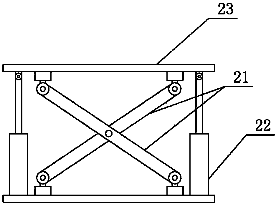
[0040] as attached figure 1 , attached figure 2 , attached image 3 , attached Figure 4 , attached Figure 5 , attached Image 6 , attached Figure 7 and attached Figure 9 As shown, a quality inspection conveying line of the present invention includes a first scanning device 291 for scanning the head of the workpiece, a first scanning device 292 for scanning the bottom of the workpiece, and a first scanning device 292 for grabbing the defective workpiece at the head. The first manipulator device 301 and the second manipulator device 302 for grabbing the bottom defective workpiece; it also includes the front conveyor belt 2 for material box 1 delivery, the rear conveyor belt 3 and the two material box 1 A clamping and flipping material turning device, wherein the material box 1 is provided with a plurality of spaced distribution chambers 101 for plac...


PUM


Abstract

The invention discloses a quality control conveying line. The quality control conveying line comprises a first scanning device (291), a second scanning device (292), a first manipulator device (301) and a second manipulator device (302). The quality control conveying line is characterized by further comprising a front conveying belt (2) and a back conveying belt (3) for conveying material boxes (1) and a material overturning device for clamping and overturning two material boxes (1), wherein the material boxes (1) are provided with multiple placing cavities distributed at intervals for placingworkpieces; an input end of the material overturning device is connected with the front conveying belt (2); an output end of the material overturning device is connected with the back conveying belt(3); the first manipulator device (301) is in signal connection with the first scanning device (291); and the second manipulator device (302) is in signal connection with the second scanning device (292). The quality control conveying line has the advantages of high automation degree and high working efficiency.

Description

technical field [0001] The invention relates to a quality inspection conveying line. Background technique [0002] After the workpiece is produced, it needs to go through the quality inspection link to judge whether the workpiece is qualified. Some workpieces are particularly prone to defects or blemishes at the head and bottom of the workpiece. It is necessary to remove defective head workpieces and bottom defective workpieces. The existing operation mode is to first detect whether there are defects in the head of the workpiece. If there are defects, use the manipulator or manually to select the defective workpieces with the head from the good ones, and then use the manipulator or manpower to turn over the workpieces whose heads have been inspected, and then check whether there are defects at the bottom of the workpiece. If there are defects, the defective workpieces at the bottom are selected from the good workpieces, and the final workpieces pass the quality inspection, ...

Claims


Application Information

Patent Timeline
Patent Type & Authority Applications(China)
IPC IPC(8): B07C5/00B07C5/02B07C5/36
CPCB07C5/00B07C5/02B07C5/3422B07C5/361B07C5/362B07C2501/0063
Inventor 黄雪位
Owner 黄雪位
Learn More