
Hot-melt field-assembled optical fiber connector

A fiber optic connector and on-site assembly technology, which is applied in the coupling of optical waveguides, etc., can solve the problems of increased cost of on-site termination, low assembly efficiency, and large communication loss of connectors, so as to save on-site assembly time and increase the success rate of assembly , the effect of reducing the overall length

Active Publication Date: 2014-01-29
NANJING PUTIAN TELEGE INTELLIGENT BUILDING
View PDF5 Cites 0 Cited by
  • Summary
  • Abstract
  • Description
  • Claims
  • Application Information

AI Technical Summary

Problems solved by technology

[0002] At present, the existing hot-melt field-assembled optical fiber connectors can only achieve one-time fusion splicing, but affected by the fusion splicer and various human factors on site, the hot-melt optical fiber connector cannot completely achieve a successful fusion splicing. If it fails, the fiber optic connector will be useless, so it will inevitably lead to an increase in the cost of on-site termination, and the operation is complicated and the assembly efficiency is low
[0003] In addition, there are usually two ways to move the optical fiber used in the hot-melt optical fiber quick connector. One is to fuse the user-end optical fiber with the preset optical fiber, and then fix it with the ferrule through the tail sleeve. When inserting the optical fiber adapter, The optical fiber at the user end moves with the ferrule, but because the tail sleeve has no limit, the user may pull the optical fiber during later maintenance and cause the communication terminal, and because part of the pulling force needs to be borne by the heat shrinkable tube, there will be some problems in later use. The risk of affecting normal use; the other is to give a small amount of redundant optical fiber at the back end of the heat shrinkable tube at the tail of the connector, so that the redundant optical fiber will bend when the ferrule is inserted into the adapter, and the insufficient length of the redundant optical fiber will cause the optical fiber to bend The radius is too small, resulting in excessive communication loss of the connector, affecting normal use

Method used


Image

  • Hot-melt field-assembled optical fiber connector
  • Hot-melt field-assembled optical fiber connector
  • Hot-melt field-assembled optical fiber connector

Examples


Embodiment

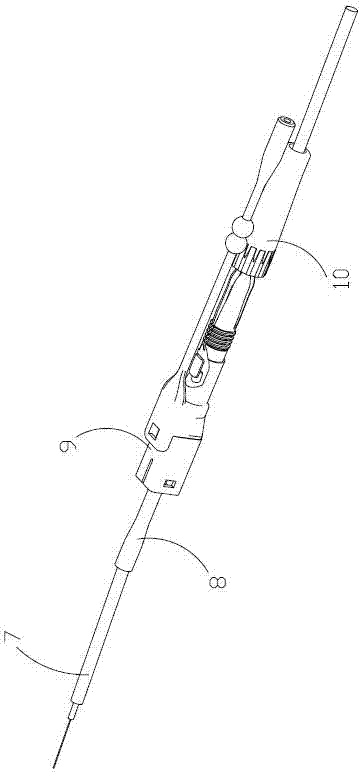
[0019] 1) First thread the screwed back seat 10, the rear bracket assembly 9, and the heat-shrinkable protection tube 8 into the user-end optical fiber 7 in sequence, and use a special tool and an optical fiber cutter to cut the user-end optical fiber 7 to a fixed length to prepare the user-end optical cable. Such as figure 1 shown.

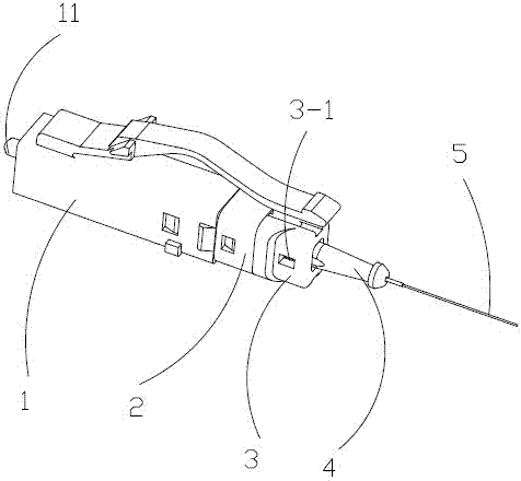
[0020] 2) The optical fiber protection part 4 is clamped in the prefabricated hole of the connecting bracket 2 through its limit card point, and the prefabricated optical fiber 5 is cut to a fixed length with an optical fiber cutter, as shown in figure 2 shown.

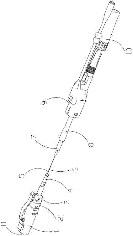
[0021] 3) Use an optical fiber fusion splicer to fuse the prepared prefabricated optical fiber and the user-end optical fiber to generate a fusion point 6, pull out the optical fiber protection member 4, and insert the limit card point into the limit hole of the ferrule 3, thereby starting to protect the prefabricated optical fiber 5, such as image 3 shown.

[0022] 4) Put the heat...


PUM


Abstract

The invention relates to a hot-melt field-assembled optical fiber connector. The connector comprises a front bracket, a connecting bracket, a ferrule, an optical fiber protector, a prefabricated optical fiber, a user side optical fiber, a heat-shrinkable protective tube, a rear bracket assembly, a screwing rear seat, an inserted core assembly and a spring. The connector has the following advantages: 1) the connector can be reused twice, thus increasing the assembly success rate, saving the field assembly time and lowering the cost; 2) the defect that the properties of the optical fiber quick connector are poorer because the bending radius of the optical fiber is insufficient, which is caused by insufficient length of the additional section, is overcome, and as the additional section of the optical fiber is the prefabricated optical fiber, the anti-bending optical fiber can be used, the bending radius is smaller, the additional section of the optical fiber can be shorter and the whole length of the optical fiber connector is reduced; 3) the optical fiber additional section welded twice is preposed, so the front end of the connector is a whole; and 4) the internal structure is suitable for various types of hot-melt field-assembled optical fiber connectors such as SC and LC and 0.25mm and 2.0mm optical cables.

Description

technical field [0001] The invention relates to a hot-melt field-assembled optical fiber connector, which belongs to the technical field of hot-melt field-assembled optical fiber connectors. Background technique [0002] At present, the existing hot-melt field-assembled optical fiber connectors can only achieve one-time fusion splicing, but affected by the fusion splicer and various human factors on site, the hot-melt optical fiber connector cannot completely achieve a successful fusion splicing. If it fails, the fiber optic connector will be useless. Therefore, it will inevitably lead to an increase in the cost of on-site termination, and the operation is complicated and the assembly efficiency is low. [0003] In addition, there are usually two ways to move the optical fiber used in the hot-melt optical fiber quick connector. One is to fuse the user-end optical fiber with the preset optical fiber, and then fix it with the ferrule through the tail sleeve. When inserting the...

Claims


Application Information

Patent Timeline
Patent Type & Authority Patents(China)
IPC IPC(8): G02B6/255
Inventor 李志宏关梦琳管陈明张绪
Owner NANJING PUTIAN TELEGE INTELLIGENT BUILDING
Learn More