
Clock-correcting method and equipment

A clock correction and equipment technology, applied in the direction of response error generation, etc., can solve problems such as abnormal equipment operation, unstable system operation, system clock jump, etc., and achieve the effect of improving reliability and stability

Active Publication Date: 2013-02-13
BEIJING XINWANG RUIJIE NETWORK TECH CO LTD
View PDF3 Cites 23 Cited by
  • Summary
  • Abstract
  • Description
  • Claims
  • Application Information

AI Technical Summary

Problems solved by technology

[0012] The embodiment of the present invention provides a method and device for clock correction, which is used to solve the problem in the prior art that when the system clock is corrected, the system clock jumps suddenly, causing the equipment in the system to work abnormally and making the system work unstable.

Method used


Image

  • Clock-correcting method and equipment
  • Clock-correcting method and equipment
  • Clock-correcting method and equipment

Examples


Embodiment 1

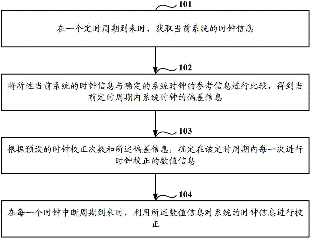
[0031] Such as figure 2 As shown, it is a flow chart of a clock correction method in Embodiment 1 of the present invention, and the method includes:

[0032] Step 101: Obtain clock information of the current system when a timing period arrives.

[0033] Wherein, the timing period may be determined according to the operating state of the system, or may be determined according to needs, and there is no limitation here.

[0034] Specifically, the timing cycle may be a fixed period of time, or a period of time, or may be performed in real time, that is, the timing cycle has no time interval.

[0035] Wherein, the timing period includes multiple clock interruption periods.

[0036] Ways to determine the arrival of the timing period include but are not limited to the following ways:

[0037] The first way: the arrival of the timing period is determined by the software program. For example: software timer.

[0038] The second way: the arrival of the timing period is determined ...

Embodiment 2

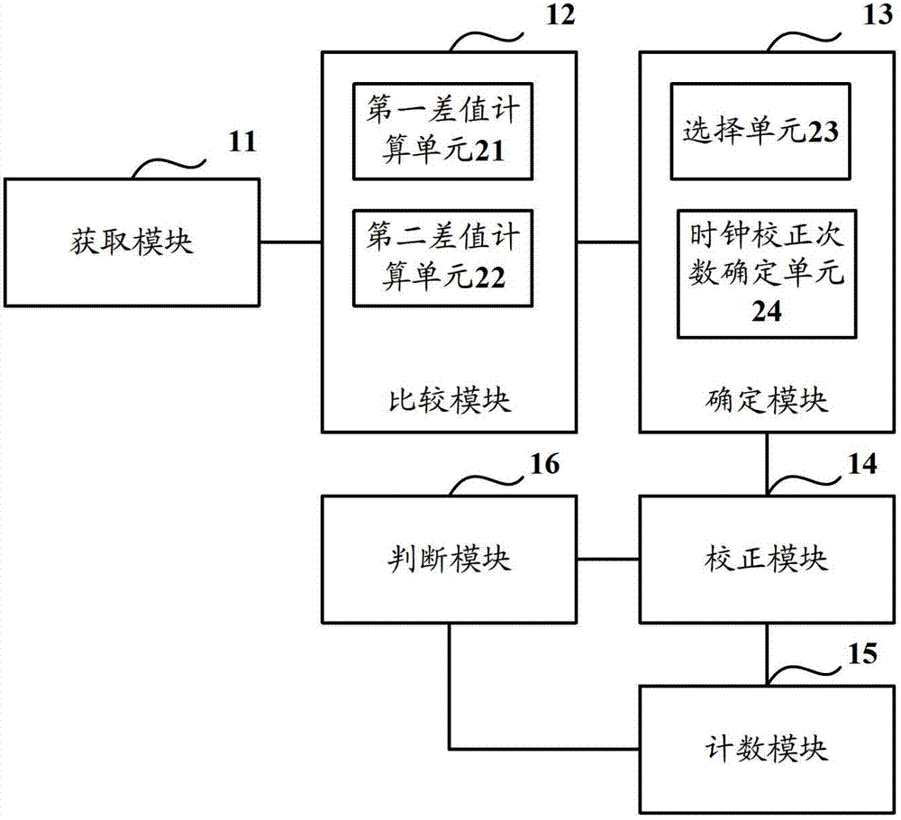
[0078] Such as image 3 As shown, it is a schematic structural diagram of a clock correction device in the second embodiment, the device includes: an acquisition module 11, a comparison module 12, a determination module 13 and a correction module 14, wherein:

[0079] Obtaining module 11, for obtaining the clock information of the current system when a timing period arrives;

[0080] A comparison module 12, configured to compare the clock information of the current system with the determined reference information of the system clock to obtain deviation information of the system clock in the current timing period;

[0081] A determination module 13, configured to determine the numerical information of each clock correction within the timing period according to the preset number of clock corrections and the deviation information;

[0082] The correction module 14 is configured to use the value information to correct the clock information of the system when each clock interrupti...


PUM


Abstract

The invention discloses a clock-correcting method and clock-correcting equipment. The clock-correcting method comprises the following steps of: acquiring the clock information of a current system when a timing cycle comes; comparing the clock information of the current system and the determined reference information of the system clock to obtain the deviation information of a system clock in the current timing cycle; determining the numerical information for every clock correction according to the preset clock correction frequency and the deviation information; and correcting the clock information of the system by using the numerical information when every clock interrupt cycle comes. By the method, the determined numerical information for correcting the clock information of the system every time is small; and the correction of the system clock is realized through a micro-adjustment mode, so that the problem that because the system clock hops suddenly due to large correction numerical information when the system clock is corrected in the prior art, equipment in the system works abnormally can be avoided, and the reliability and stability of the system are improved.

Description

technical field [0001] The invention relates to the field of computer applications, in particular to a clock correction method and equipment. Background technique [0002] The so-called embedded system refers to a non-PC system, a device or equipment that has computer functions but is not called a computer. A dedicated computer system with comprehensive and strict requirements on volume and power consumption. Among them, the embedded system is mainly composed of an embedded processor (that is, an embedded CPU), related supporting hardware, an embedded operating system, and an application software system. The operating system that an embedded system runs is called an embedded operating system. [0003] Generally, in embedded systems, clock-related concepts include: hardware clock, system clock, frequent clock cycles, clock ticks, and system clocks that are too slow or too fast. [0004] The so-called hardware clock refers to the clock powered by the battery on the motherbo...

Claims


Application Information

Patent Timeline
Patent Type & Authority Applications(China)
IPC IPC(8): G06F11/07
Inventor 梁恩波
Owner BEIJING XINWANG RUIJIE NETWORK TECH CO LTD
Learn More