Surge current suppression circuit and lamp

A technology for suppressing circuits and inrush currents, which is applied in the layout of electric lamp circuits, emergency protection circuit devices for limiting overcurrent/overvoltage, circuit devices, etc. and other problems, to achieve the effect of small size and low cost

Active Publication Date: 2013-02-13
OCEANS KING LIGHTING SCI&TECH CO LTD +1
View PDF4 Cites 6 Cited by
  • Summary
  • Abstract
  • Description
  • Claims
  • Application Information

AI Technical Summary

Benefits of technology

This patented technology helps prevent damage caused by overcurrent flow during normal operation without reducing its effectiveness or increasing costs compared with existing methods such as fuse circuits that are bulky and expensive. It uses resistors instead of traditional components like transistors for better performance while maintaining their compact design.

Problems solved by technology

The technical problem addressed by this patented technology relates to prevention of excessive voltage from being applied across electronic equipment during times when there're no electricity available for use due to accidental damage caused by high voltages that could occur if too much charge was left on certain parts of these systems.

Method used


Image

  • Surge current suppression circuit and lamp
  • Surge current suppression circuit and lamp
  • Surge current suppression circuit and lamp

Examples


Embodiment Construction

[0016] In order to make the object, technical solution and advantages of the present invention clearer, the present invention will be further described in detail below in conjunction with the accompanying drawings and embodiments. It should be understood that the specific embodiments described here are only used to explain the present invention, not to limit the present invention.

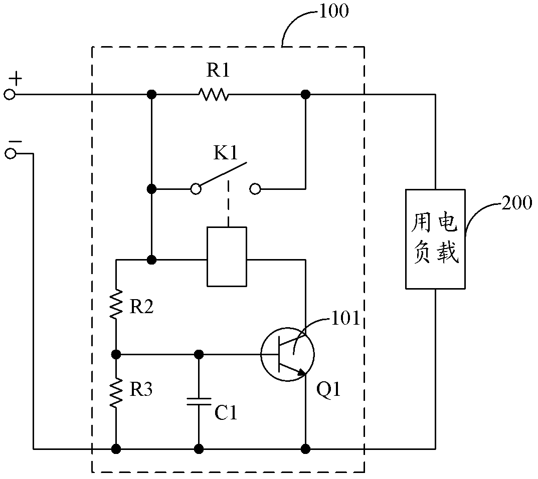
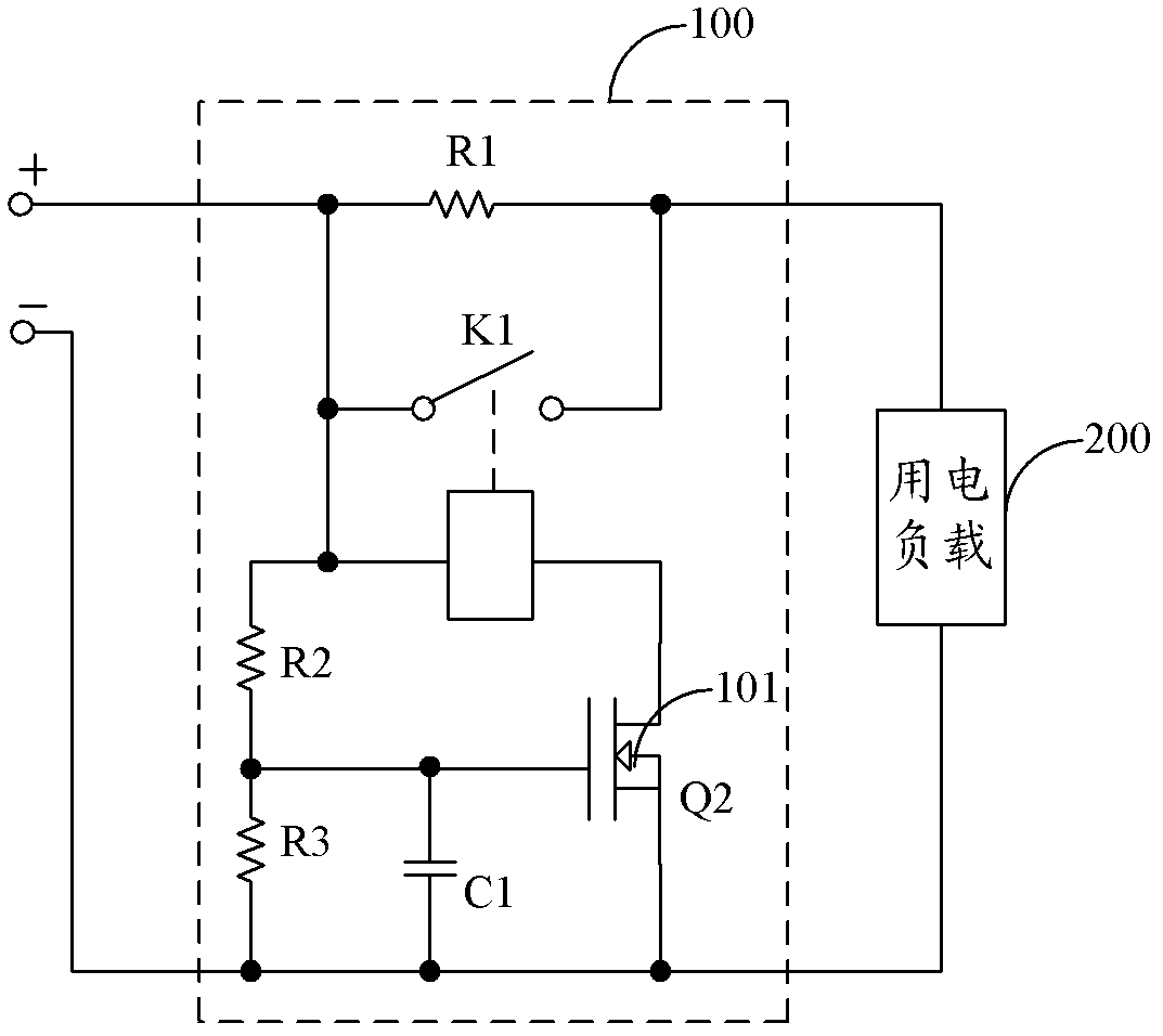
[0017] figure 1 The circuit structure of the surge current suppression circuit provided by the first embodiment of the present invention is shown. For the convenience of description, only the parts related to the embodiment of the present invention are shown, and the details are as follows.

[0018] The surge current suppression circuit 100 is connected between the power supply and the electric load 200, and the surge current suppression circuit 100 includes:

[0019] Resistor R1, voltage dividing resistor R2, voltage dividing resistor R3, relay K1, switch tube 101 and ceramic chip capacitor C1; ...


PUM


Abstract

The invention is suitable for the field of protection circuits and provides a surge current suppression circuit and a lamp. The surge current suppression circuit comprises a resistor R1, a relay K1, a switching tube and a porcelain capacitor C1; the switching tube is at an off state at the instant of electrifying the circuit when voltages at two ends of the porcelain capacitor C1 are not high enough to reach the threshold voltage of the control end of the switching tube, and a coil circuit of an electromagnet of the relay K1 is open-circuited, a switch of the relay K1 is powered off, the current loop of an electric load needs to pass through the resistor R1 to form a working loop, and the surge current generated at the instant of electrifying can be eliminated by the resistor R1; and after the surge current peak passes, when the voltages at two ends of the porcelain capacitor C1 reach the threshold voltage at the control end of the switching tube, the switching tube is at an on state, the switch of the relay K1 is switched on, and therefore the resistor R1 is separated from the working circuit. The surge current suppression circuit has the advantages of small size, low cost and incapability of reducing the electric efficiency of a protected circuit.

Description


Claims


Application Information

Patent Timeline
Owner OCEANS KING LIGHTING SCI&TECH CO LTD
Why Eureka
Try Eureka